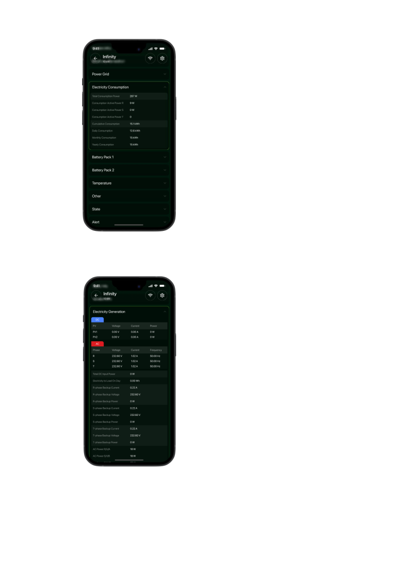
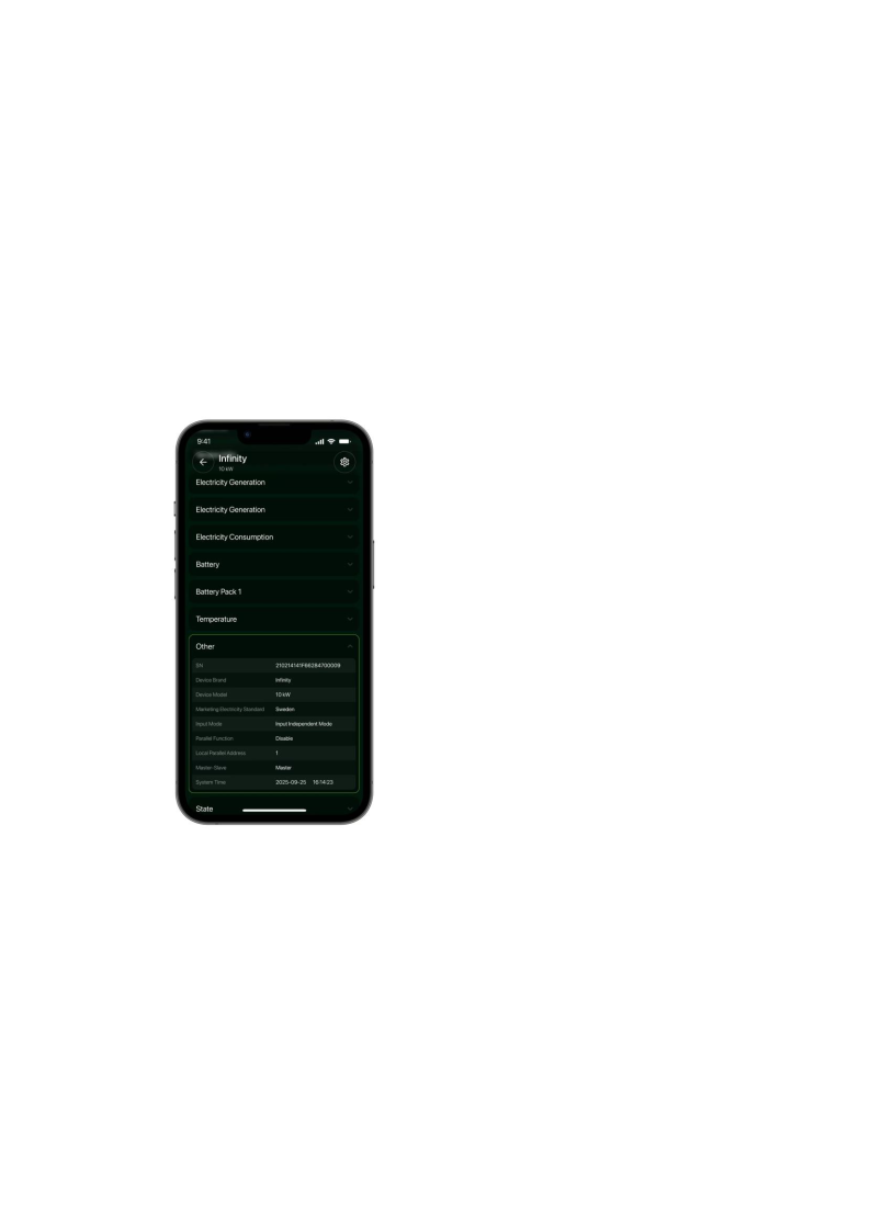
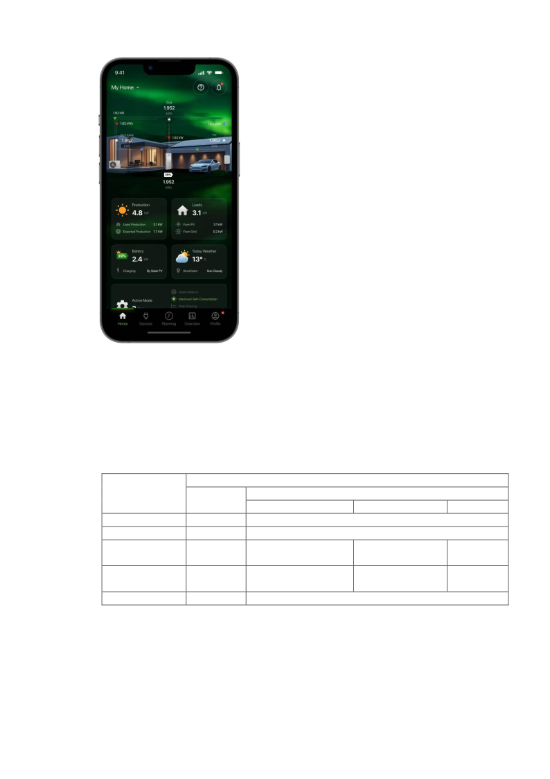
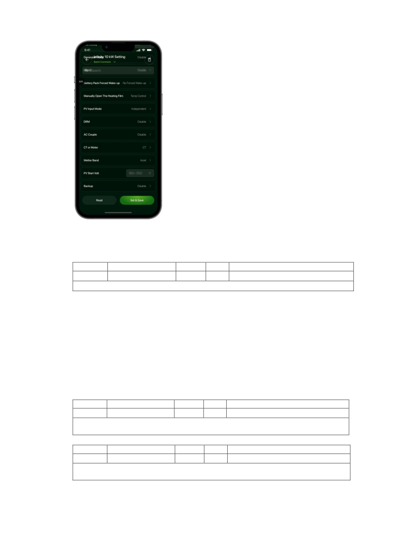
← Infinity

Infinity manual

V1.1 · For review

    Cover

    Original PDF
    Installation, Operation & Maintenance Manual INF-4-0 · INF-5-0 · INF-6-0 · INF-8-0
    INF-10-0 · INF-10-0-BE · INF-12-0
    Energy Storage System
    2026.08
    V1.1

    Contents · 1

    Original PDF

    Contents · 2

    Original PDF

    Contents · 3

    Original PDF

    Page 1

    Original PDF
    Legal Statement
    All material appearing on this manual (“content”) is the property of Green Hero AB (“Company”). Distributing, copying, or forwarding any content to a third party or uploading any content to third-party platforms (such as publicly accessible websites) without prior permission of Company is expressly prohibited.
    Trademarks and Permissions
    All other trademarks or registered trademarks are the property of their respective owners.
    Software License
    Company reserves all rights to the firmware and software. You may not use any of the data in the firmware or software for commercial purposes in any way.
    Reverse engineering, decompiling, disassembling, adapting, implanting, or other derivative operations on the equipment are prohibited, as are researching the design and implementation of the equipment, obtaining the source code, infringing on intellectual property rights in any way, and disclosing the results of any performance tests.
    Disclaimer
    Before transporting, storing, installing, using, and/or maintaining the equipment, read this manual, adhere strictly to its prescriptions, and pay attention to the labels on the equipment. In this manual,
    • “Equipment” refers to the hardware products, firmware, software, components, spare parts,
    • And /or services to which this manual relates.
    • “You” or “your” refers to an individual or a legal entity transporting, storing, installing, using,
    and/or maintaining the equipment.
    In addition to paying proper attention to content in this manual labelled DANGER, WARNING, CAUTION, and NOTICE, you shall comply with relevant international, national, or regional standards, and industry practices. Company shall not be liable for any damages resulting from violations of safety requirements or safety standards for the design, manufacturing, and use of the equipment. Company is not responsible for damage, personal injuries, death, and/or loss of or damage to property caused by use outside the scope of the conditions, technical specifications, or instructions provided in this manual. Transport, storage, installation, use, maintenance, and all other operations shall comply with applicable laws and regulations, standards, and specifications. Company shall bear no liability in any of the following circumstances:
    1

    Page 2

    Original PDF
    • The equipment is damaged due to earthquakes, floods, volcanic eruptions, mudslides,
    lightning strikes, fires, wars or armed conflicts, typhoons, hurricanes, tornadoes, extreme weather, or other force majeure events.
    • The equipment is used outside the scope of the conditions, technical specifications, or
    instructions provided in this manual.
    • Installation and/or use do not comply with relevant international, national, or regional
    standards or regulations.
    • The equipment is installed or operated by unqualified personnel.
    • The equipment is operated in a manner not in accordance with the prescriptions of the
    instruction manual and safety labels.
    • The equipment and/or software code is disassembled and/or modified without the permission
    of Company.
    • The equipment is damaged while being transported by you or a third party commissioned
    by you.
    • The equipment is stored in conditions that do not meet the standards specified in this manual.
    • In the course of operating or maintaining the equipment, you use your own materials and
    tools that do not meet the requirements of local laws, regulations, and standards.
    • Damage is caused by you or a third party through negligence, willful misconduct, gross
    negligence, or mishandling, or for other reasons not attributable to Company.
    2

    Page 3

    Original PDF
    1
    About This Manual
    This manual contains important information on the transport, storage, installation, use, and maintenance of the equipment. Read this manual carefully before operation. You must use the equipment strictly in accordance with the instructions in this manual to prevent damage or loss to the equipment, persons, and/or property. Keep this manual for future reference.
    1.1
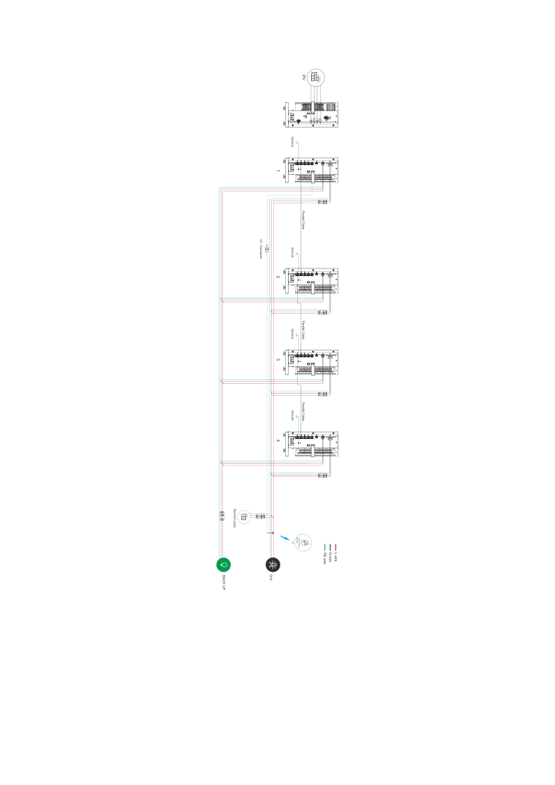
    Purpose
    This manual is intended as:
    • An introduction to a three-phase hybrid inverter (the INF-4-0/INF-5-0/INF-6-
    0/INF-8-0/INF-10-0/INF-10-0-BE/INF-12-0), and the INF-0-5.12 lithium-ion battery pack.
    • An installation and maintenance guide for qualified personnel and technicians
    working with the hybrid inverters.
    • An operating guide for qualified personnel, technicians, and users of the energy
    management system (EMS) integrated in the hybrid inverter.
    This manual does not cover all components in a PV system. For more information, see the websites of the component manufacturers.
    1.2
    Intended Audience
    The intended audience of this manual is:
    • The qualified professional personnel and technicians who install, operate, and
    maintain residential photovoltaic energy storage systems that include an INF-4- 0/INF-5-0/INF-6-0/INF-8-0/INF-10-0/INF-10-0-BE/INF-12-0 hybrid inverter, and/or the INF-0-5.12 battery pack.
    • Users who need to view inverter parameters.
    • System integration solution providers.
    3

    Page 4

    Original PDF
    1.3
    Conventions
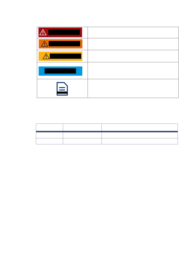
    The following symbols are used in this manual to highlight important information.
    Indicates a hazardous situation that, if not avoided, will result in death or severe injury.
    DANGER
    Indicates a hazardous situation that, if not avoided, could result in death or severe injury.
    WARNING
    Indicates a hazardous situation that, if not avoided, could result in minor or moderate injury.
    CAUTION
    Indicates information that is considered important but is not hazard related, typically used for activities that result in property damage, but no personal injury.
    NOTICE
    Indicates an important tip that leads to the best results, but not safety or damage related.
    NOTE
    1.4
    Change History
    Here is the change history of this manual.
    Version
    Date
    Changes
    1.0
    2025-12
    - Initial release.
    1.1
    2026-08
    - Model naming and legal text corrected.
    4

    Page 5

    Original PDF
    2
    Safety Instructions
    All the safety instructions in this section help you transport, store, install, use, and maintain the equipment safely, so be sure to read and follow them. In addition to these safety instructions, you must comply with the requirements of international, national, or regional standards and regulations, and you are encouraged to follow industry best practices.
    The equipment must be transported, installed, and maintained by trained professionals who fully understand how the equipment works, have sufficient training and experience in operating the equipment, and know the possible dangers and their levels. Trained personnel are those who have received relevant technical and safety training and have relevant experience. They know the possible dangers they may face when operating the equipment and how to take steps to minimize the dangers to themselves and others.
    2.1
    Limitation of Liability
    Company is not responsible, directly or indirectly, for any damage to the equipment or loss of property caused by the following:
    • Disassembling and/or modifying the equipment, replacing parts, or modifying the
    software code without the permission of the manufacturer.
    • Altering, repairing, and erasing serial numbers or seals by technicians not
    certified by the manufacturer.
    • Installation and/or operation of the equipment by unqualified personnel.
    • Installing the inverter in any way that does not comply with standards or regulations.
    • Failure to comply with local safety regulations. For example, in Germany,
    equipment must comply with VDE certification and in Australia it must comply with SAA certification.
    • Operation of the equipment in an environment with insufficient ventilation.
    • Use not in accordance with the instruction manual, technical specifications, and/
    or any other instruction provided.
    • Use of your own materials and tools that do not meet the requirements of local
    laws, regulations, and standards.
    • Failure to follow standard maintenance procedures.
    • Earthquakes, floods, volcanic eruptions, mudslides, lightning strikes, fires, wars,
    armed conflicts, typhoons, hurricanes, tornadoes, extreme weather, or other force majeure events.
    Additionally, Company is not responsible, directly or indirectly, for:
    • Damage sustained during transportation, including paint scratches caused by
    friction inside the package during transportation, and damage sustained while being transported by you or a third party commissioned by you. You must file claims with the shipping or insurance company when the container and/or the package is unloaded and the damage is confirmed.

    Page 6

    Original PDF
    • Any other damage caused by you or a third party through negligence, willful
    misconduct, or mishandling, or for other reasons not attributable to Company.
    2.2
    Warning Signs
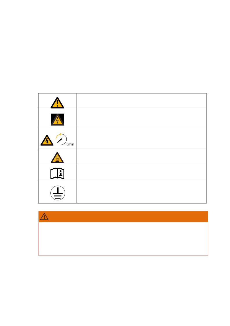
    The warning signs and nameplates attached to the equipment contain important information to guide you in safe use of the equipment. DO NOT remove, obscure, or damage these signs. Make sure that these signs are always intact and fixed in their correct positions. If a warning sign is damaged, contact the manufacturer and have it replaced immediately by certified technicians.
    You can see these warning signs attached to the equipment.
    Indicates a hazardous situation that, if not avoided, can result in death or severe injury!
    CAUTION, RISK OF ELECTRIC SHOCK symbol indicates important safety instructions, which if not correctly followed, could result in electric shock.
    Indicates that the inverter should NOT be touched or used for at least five minutes after it is turned off or disconnected, in order to prevent electric shock or personal injury.
    Indicates a hot surface. Contact can cause burns.
    Indicates that you should read the user manual for instructions.
    The ground shall be connected.
    WARNING
    After the equipment is unpacked,
    • Check all the warning signs and nameplates on the equipment.
    • If you find any damages to the warning signs and/or nameplates on the
    contact the manufacturer immediately. Do not install the equipment.
    6

    Page 7

    Original PDF
    WARNING
    Before disposal, make sure that all warning signs and nameplates are clearly visible and are not removed or obscured.
    WARNING
    When you instruct others in use of the equipment, and maintain and/or repair the equipment, follow these instructions to prevent inappropriate use or accidents caused by uninvolved persons:
    • Place clear signs at the front and rear-level switches to prevent accidents
    caused by inappropriate switching.
    • Place a warning sign or safety caution tape around the operating area.
    • If the equipment is used in a manner not specified by the manufacturer, the
    protection provided by the equipment may be impaired.
    WARNING
    Do not damage the grounding conductor, and do not operate the product before the grounding conductor is properly installed. Failure to follow these instructions may result in personal injury or product damage. Please select a measuring device with an appropriate range. Overvoltage may damage the measuring device and cause personal injury.
    WARNING
    External protective earthing terminal shall meet at least one of the following requirements:
    • When the cross-sectional area of the earthing cable is ≥10mm2(copper) or ≥ 16mm2 (aluminum), it is recommended that both the external protective earthing terminal and the AC side earthing terminal are grounded.
    • When the cross-sectional area of the earthing cable is <10mm2 (copper) or <16mm2 (aluminum), **ensure that** both the external protective earthing terminal and the AC side earthing terminal are grounded. If alternative earthing methods comply with local standards and relevant safety regulations, the connection may be performed according to such standards and regulations. Our company shall not be held liable for any consequences that may arise therefrom.
    7

    Page 8

    Original PDF
    2.3
    Battery Safety
    A rechargeable lithium-ion phosphate battery is used in the equipment. The battery complies with the provisions of “United Nations Recommendations on the Transport of Dangerous Goods, Manual of Tests and Criteria, Part III, Section 38.3”.
    Company shall not be responsible for:
    • Damages to the battery caused by earthquakes, floods, volcanic eruptions,
    mudslides, lightning strikes, fires, wars, armed conflicts, typhoons, hurricanes, tornadoes, extreme weather, or other force majeure events.
    • Direct damage caused by operation of the equipment in environments other than
    the intended operating environment. Indicators of inappropriate environments include, but are not limited to, excessively high or low operating temperatures, instability of the power grid, and frequent power outages.
    • Damage, leakage, and/or rupture caused by inappropriate operation or failure to
    connect the battery pack in accordance with requirements.
    • Damage caused by over-discharge of the battery due to the failure of operating
    personnel to promptly power up the battery after it has been connected to the system.
    • Damage caused by your failure to accept the battery in time after installation.
    • Damage caused by inappropriate parameters that you set.
    • Accelerated battery capacity degradation caused by mixing of batteries,
    including, but not limited to, the mixing of batteries of different brands and mixing of batteries with different rated capacities.
    • Battery damage caused by storing the battery in an unintended environment,
    such as in a humid, rain-prone environment.
    • Loss of capacity or irreversible damage to the battery caused over-storage
    without recharging the battery in a timely manner.
    • Damage caused by your or a third party’s failure to follow the requirements
    specified by the manufacturer, including, but not limited to, unauthorized relocation and installation of the battery packs.
    Company shall not be responsible for damage caused by:
    • Frequent over-discharge of batteries caused by your inappropriate maintenance,
    on-site expansion, or long-term failure to fully charge.
    • Lack of appropriate maintenance in accordance with the operating manual. Such
    battery maintenance should include, but is not limited to, regular checks of the battery terminal screws to verify tightness.
    • Changing the battery usage scenario without the approval of the manufacturer.
    • Unapproved connection of additional loads to the battery.
    • Batteries exceeding the maximum storage life.
    • Batteries exceeding the warranty period. Such batteries can pose hazards and it
    is not recommended that you continue to use them.
    8
    Page 9

    Original PDF
    2.3.1
    General Instructions
    The chemical substances inside the battery are well sealed, so there is no physical danger of fire or explosion or chemical danger of hazardous material leakage at normal temperatures and pressure levels during handling. If the battery pack is exposed to fire, mechanical shock, decomposition, or increased electrical stress due to misuse, then leakage, release of harmful substances, and/or explosion can occur. The released substances can irritate the eyes, skin, and throat.
    • Only trained professionals are permitted to handle
    DANGER
    leaking batteries.
    • When handling leaking batteries, personnel must wear
    goggles, rubber gloves, gas masks, and protective clothing.
    • When handling leaking batteries, personnel must
    first disconnect the equipment and then remove the leaking batteries.
    • Batteries should be protected from the following:
     Short circuit caused by live line maintenance or by
    shorting the positive and negative terminals of the battery.
     Exposure to high temperature or heating equipment,
    such as direct sunlight, ignition sources, transformers, or heaters.
     Squeezing by an external force or immersion in
    water or other liquids.
     Over-charging or forced over-discharging.  Exposing battery terminals to other metal objects.  The use of incorrect battery types.
    Batteries should be protected from the following:
    WARNING
    • Malfunctions or short circuits caused by liquid
    entering the battery. Therefore, DO NOT install the battery pack under air conditioning outlets, ventilation vents, machine room outlet windows, water pipes, and other locations prone to water leakage.
    • Inverted, sideways, tilted, or stacked placement.
    • False connection of fastening screws of the copper
    row and/or the cable, which can cause excessive voltage drop or the generation of a large amount of heat at higher current, which could burn the battery.
    9

    Page 10

    Original PDF
    2.3.2
    Maintenance of Battery Packs
    • DO NOT perform live line maintenance on the
    DANGER
    batteries to prevent short circuit.
    • Use the specified type of battery during replacement.
    • Do a regular check on the fastening screws of copper
    WARNING
    rows and/or cables. Make sure that they are tightened and free of rust, corrosion, or other foreign objects. If they are not, clean them.
    2.3.3
    Disposal of Battery Packs
    • Before disposal, completely discharge the battery and
    WARNING
    consume the lithium metal inside the battery.
    • DO NOT treat unwanted batteries as ordinary waste.
    • DO NOT throw the battery pack into fire or place them in
    high temperature.
    • DO NOT dissect, pierce, or crush the batteries.
    • If a battery pack is deformed, broken, or leaking,
    discard it immediately regardless of how long it has been in storage.
    10

    Page 11

    Original PDF
    2.4
    Before Installation
    • Follow the safety instructions in this manual to prevent
    DANGER
    personal injury and/or property damage.
    • During transportation, a certified ABC fire extinguisher
    with a capacity of at least 2 kg must be with the equipment.
    • Smoking is not permitted on or near the vehicle while
    loading or unloading.
    • Before installation, make sure that the equipment is
    free of any electrical connections.
    • Make sure that no water pipes are inside the wall on
    which the system is to be mounted.
    • To prevent possible electric shock, make sure that the
    inverter is not damaged and that the inverter and all switches connected to it are set to the “OFF” position.
    • Before installation, use a properly calibrated voltage
    meter to test the inverter to prevent personal injury or damage caused by a life-threatening voltage.
    • The PV string exposed to sunlight can generate high
    voltage. Do these to prevent personal injury:  The operator must wear personal protective
    equipment before electrical connection.
     Before touching DC cables, use a measuring device
    to make sure that the cables are not energized.
     Read the safety instructions attached to the PV
    string and its manuals.
     DO NOT connect the inverter to a PV string that
    requires positive or negative grounding.
    11

    Page 12

    Original PDF
    • DO NOT transport equipment in severe weather such
    WARNING
    as lightning, rain, snow, or winds of force 6 or higher.
    • If there is a fire, evacuate the building or equipment
    area and ring the fire alarm. DO NOT enter a burning building or equipment area.
    • Choose an appropriate and safe place to install the
    equipment. This place must meet these requirements:  Temperature: For the inverter and battery pack.
    See Specifications.
    ▪ Relative humidity: 0–95% (No condensation). ▪ NO flammable or explosive materials. ▪ NOT accessible to children. ▪ NO salt hazards. ▪ Sheltered from direct sunlight or severe weather. ▪ NOT subject to strong vibration or electromagnetic fields.
     Well ventilated  NOT a living area.
    • A distance of at least 30 mm must be maintained
    between the cable and a heat generating device or the periphery of a heat source area to prevent deterioration and/or breakage of the cable insulation caused by high temperature.
    • DO NOT install the equipment that is infiltrated by
    moisture.
    • DO NOT install the equipment with damaged
    enclosure and exposed to moisture.
    • Only qualified personnel are permitted to transport the
    CAUTION
    equipment.
    • Loading, unloading, installation, removal, and
    transportation of inverters and battery packs must be accomplished by two or more persons to prevent personal injury caused by accidental falling equipment.
    • If lifting tools are used to lift the equipment,
    make sure that no one passes or stays under the equipment.
    • Before installation, do a regular check and
    NOTICE
    maintenance on the tools.
    12

    Page 13

    Original PDF
    2.5
    Installation Safety
    • To avoid personal injury caused by the high voltage
    DANGER
    inside the equipment:  Use special insulated tools for wiring.  Read the warning signs on the equipment and
    follow their instructions.
     Follow the safety instructions in this manual and
    other documents provided.
    • Only trained professionals are permitted to install the
    equipment.
    • Only qualified personnel are permitted to disassemble
    the safety features and to service the equipment.
    • Only the personnel who have the special operation
    qualification required by national or local authorities are permitted to work in special scenarios such as electrical operation, work at heights, and operation of special equipment.
    • Only INFINITY-approved professional personnel
    are permitted to replace the equipment or spare parts (including software).
    • DO NOT power up the equipment before the installation
    is completed and confirmed by trained professionals.
    • Avoid direct contact with the power supply equipment,
    as well as indirect contact through wet objects. Prevent other conductors from coming into contact with the power supply equipment. Measure the voltage at the point of contact before you touch any conductor surface or terminal, so as to avoid electric shock.
    • Use appropriate measuring tools to make sure that the
    electrical parameters of the equipment meet the requirements. To prevent electric arcs or shocks, make sure that the connection and use of the equipment comply with the specifications.
    13

    Page 14

    Original PDF
    • DO NOT install equipment in severe weather such as
    WARNING
    lightning, rain, snow, or winds of force 6 or higher.
    • If there is a fire, evacuate the building or equipment
    area and ring the fire alarm, or call the emergency services. DO NOT enter a burning building or equipment area.
    • It is recommended that you install the inverter
    vertically, not inverted, horizontal, tilted forward or backward, excessively tilted, or tilted sideways.
    • When tightening screws or bolts on products or
    terminals with tools, tighten to the specified torque to prevent damage to the equipment. The manufacturer shall not be responsible for such damage.
    • DO NOT touch the equipment surface when the
    equipment is in operation. The housing gets hot, and touching it can result in burns.
    • The cables used in the PV system must be of the right
    size, firmly connected, and well insulated.
    • Before connecting the DC connector to the inverter,
    check the positive and negative terminals of the PV string and make sure that no error occurs before inserting the DC connector into the DC terminal.
    • During the installation of the inverter, make sure that
    neither the positive nor the negative terminal of the PV string is shorted to ground, to prevent damage caused by AC/DC short circuit of the inverter.
    • To prevent uninvolved persons from approaching the
    CAUTION
    equipment, place highly visible warning signs or set up safety caution tape around the equipment.
    • DO NOT remove the equipment protection.
    • DO NOT ignore the danger, warning, caution, and
    notice text in the manuals and on the equipment.
    • The wiring process must follow the regulations of the
    NOTICE
    local grid and the safety instructions for the PV string.
    14

    Page 15

    Original PDF
    2.6
    Operation Safety
    • Follow the safety instructions in this manual to
    DANGER
    prevent personal injury and/or property damage.
    • The person who operates the equipment must have
    necessary knowledge of the equipment, including the equipment components and how they work.
    • The person who operates the equipment must have
    necessary knowledge of this manual.
    • Only qualified personnel are permitted to disassemble
    the safety features and to service the equipment.
    • Keep persons other than those operating the equipment
    away from the equipment .
    • DO NOT operate the equipment in an environment
    where explosions can occur, or where the relative humidity is high.
    • When the equipment is in operation,
     DO NOT open the inverter and the battery packs.  DO NOT wipe the equipment with a wet cloth.  DO NOT touch the housing of the equipment.  DO NOT plug or unplug connectors on the inverter.  To avoid electric shock, DO NOT touch any terminals of
    the inverter.
     To avoid electric shock, DO NOT disassemble any
    parts of the inverter.
     To avoid burns, DO NOT touch any hot parts of the
    inverter, such as radiator.
     To avoid electric shock, DO NOT connect or
    disconnect a PV string or a component of a PV string.
    • To avoid fatal electric shock, DO NOT touch the DC
    conductors or energized electrical parts of the inverter. When PV arrays are exposed to sunlight, they can generate life-threatening DC voltage. This voltage can be present in DC conductors and in the energized electrical parts of the inverter.
    • To avoid electric shocks and burns caused by
    possible arcs, DO NOT disconnect the DC connector from the inverter under load.
    • Before operating the inverter or the battery packs,
    disconnect the inverter from all voltage sources as described in this manual.
    • DO NOT touch uninsulated cable ends.
    15

    Page 16

    Original PDF
    • To prevent chemical burns caused by leakage of
    electrolyte or toxic gases from a damaged battery, operate the battery packs in accordance with the standard procedure. When the battery packs are operated in a standard manner, no leakage of electrolyte or generation of toxic gases can occur. However, if the battery packs are damaged or malfunction, it can leak electrolyte or generate toxic gases.
    • DO NOT operate equipment in severe weather such
    WARNING
    as lightning, rain, snow, or winds of force 6 or higher.
    • DO NOT touch the equipment with wet hands.
    • DO NOT put any heavy objects on the top of the
    equipment.
    • DO NOT damage the equipment with sharp objects.
    • To prevent uninvolved persons from approaching the
    CAUTION
    equipment, place highly visible warning signs or set up safety caution tape around the equipment.
    • DO NOT move the inverter when it is connected to
    the battery packs.
    • Secure the inverter to prevent tilting.
    • During the operation of the equipment, if any risks are
    found that may lead to personal injury or equipment damage, stop the operation immediately, report to the person in charge, and take effective steps.
    • During the operation of the inverter, make sure that
    neither the positive nor the negative terminal of the PV string is shorted to ground, to prevent damage caused by AC/DC short circuit of the inverter.
    • In the event of exposure to the electrolyte,
    NOTICE
    immediately flush the affected area with water and seek immediate medical attention.
    16

    Page 17

    Original PDF
    2.7
    Maintenance Safety
    • Follow the safety instructions in this manual to
    DANGER
    prevent personal injury and/or property damage.
    • Only trained professionals are permitted to maintain
    the equipment.
    • Only qualified personnel are permitted to disassemble
    the safety features and to service the equipment.
    • Keep persons other than those operating the
    equipment away from the equipment.
    • Wear personal protective equipment (PPE), including
    protective gloves and protective shoes.
    • DO NOT begin maintenance work on the equipment
    until it is turned off and fully discharged.
    • Before maintenance, disconnect the AC circuit breaker
    from the grid and check the inverter status. If all the inverter indicator lights are off, do nothing and disconnect the DC switch at night. If the inverter indicator is on, disconnect the DC switch directly.
    • After the inverter is powered down for five minutes,
    use testing equipment to check the voltage of the bus capacitor and of the capacitors in the battery terminal input and make sure that there is no voltage.
    • To avoid burns, DO NOT operate the equipment
    immediately after shutdown. After the equipment cools down, wear protective gloves to operate the equipment.
    • DO NOT maintain equipment in severe weather such
    WARNING
    as lightning, rain, snow, or winds of force 6 or higher.
    • To avoid electric shock, DO NOT touch the power grid
    or the contacts and terminals inside the equipment that are connected to the grid.
    • Use a standard voltmeter to check the grid. DO NOT
    touch the grid before you make sure that there is no voltage.
    • To prevent or to minimize potential damage caused by
    moisture, DO NOT repair or maintain the equipment in a wet environment.
    • To prevent uninvolved persons from approaching the equipment, place highly visible warning signs or set up safety caution tape around the equipment.
    CAUTION
    17

    Page 18

    Original PDF
    • If the paint on the inverter housing falls off or rust
    NOTICE
    appears, repair it in a timely manner. Otherwise, the use of the inverter may be affected.
    • To avoid damaging the inverter, DO NOT use cleaning
    agents to clean the inverter. The manufacturer shall not be responsible for such damages.
    • DO NOT open the inverter (excluding the cable box)
    and replace the components inside without the permission of the manufacturer.
    2.8
    Disposal Safety
    • Only trained professionals are permitted to discard
    DANGER
    the equipment.
    • Before disposal, make sure that all warning signs
    WARNING
    and nameplates are clearly visible and have not been removed or obscured.
    • To prevent property damage and personal injury, dispose
    of equipment in accordance with local regulations and standards.
    3
    Product Introduction
    3.1
    Features
    The INF-4-0/INF-5-0/INF-6-0/INF-8-0/INF-10-0/INF-10-0-BE/INF-12-0 is a residential photovoltaic storage system that is composed of a power control module and an extendable battery pack. It stores and releases electrical energy according to the inverter management system requirements. Company provides a photovoltaic storage-monitoring platform to monitor and control electricity generation and storage of the INF-4-0/INF-5-0/INF-6-0/INF-8-0/INF-10-0/INF-10-0- BE/INF-12-0 . Power generation, consumption, and storage can be grasped at any time and any place, and the information can be monitored and controlled remotely. The INF-4-0/INF-5-0/INF-6-0/INF-8-0/INF-10-0/INF-10-0-BE/INF-12-0 comes with an integrated energy management system (EMS). This system enables the inverter to run off-grid or on-grid and manages energy flow intelligently so that the system can operate economically.
    3.2
    Delivery Scope
    18

    Page 19

    Original PDF
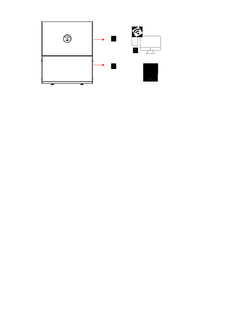
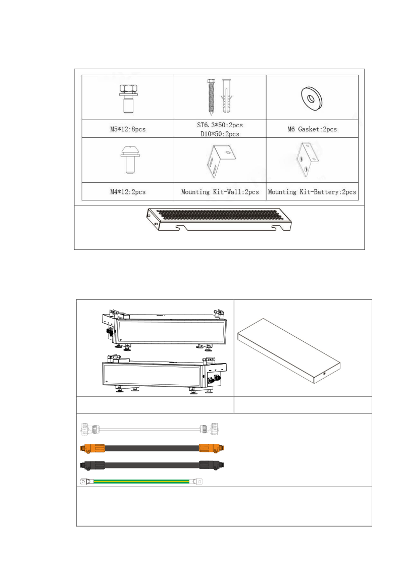
    Figure 3-1 INF-4-0/INF-5-0/INF-6-0/INF-8-0/INF-10-0/INF-10-0-BE/INF-12-0 Delivery
    1
    Hybrid inverter (with integrated Energy Management System).
    2
    Battery packs, extendable.
    3
    GREEN HERO, for remote monitoring, available in a web-based portal and an APP. For more information, see Dongle Quick Guide. Stick logger, to be connected to the inverter. For more information, see Wi-Fi LAN Dongle Quick Guide.
    4
    19

    Page 20

    Original PDF
    3.3
    Model
    3.3.1
    Inverter Model
    The hybrid inverter model is INF-4-0/INF-5-0/INF-6-0/INF-8-0/INF-10-0/INF-10-0- BE/INF-12-0 .
    INF - 4 - 0
    1
    “INF” means “Infnity”.
    “x” indicates the rated output of the system. “4” means 4 kW, “5” means 5 kW,
    2
    and “6K” means 6 kW, “8K” means 8 kW, “10K” means 10kW, “12” means
    12 kW.
    3
    “0” means 0 kWh. Values such as 5, 12, 10 or 24 indicate a package with batteries.
    3.3.2
    Battery Pack Model
    INF 0
    5.12
    1
    ““INF” means “Infnity”.
    2
    “0” means “0=kW if 4, 6, 8, 10, 12 ....Then it’s a package with inverter ”.
    3
    “5.12” means the battery Rated energy: is 5.12kWh.
    20

    Page 21

    Original PDF
    3.4
    Inverter Appearance
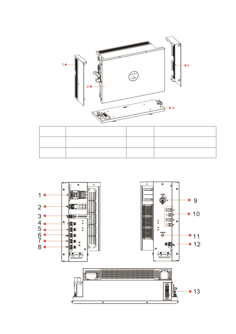
    Item
    Describe
    Item
    Describe
    1
    Left decorative panel
    2
    LED display panel
    3
    Right decorative panel
    4
    Floor stand support
    Figure 3-2 The main components exploded diagram in the inverter packaging box
    3.5
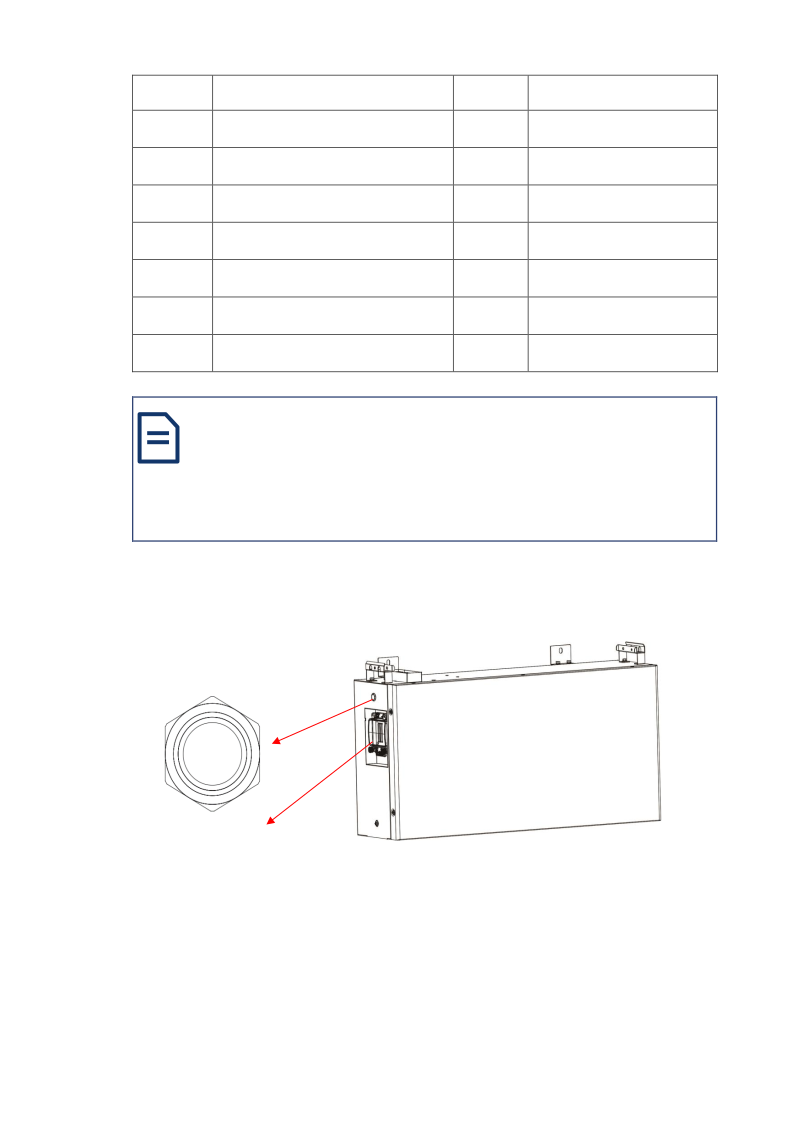
    External ports on the inverter
    Figure 3-3 External Interface
    21

    Page 22

    Original PDF
    Item
    Describe
    Item
    Describe
    1
    2
    GRID(DVC C)
    BACK UP(DVC C)
    WLAN/4G/LAN (DVC A)
    3
    4
    CT(DVC A)
    5
    6
    DRM(DVC A)
    DRY&METER (DVC A)
    7
    8
    Parallel1(DVC A)
    Parallel2(DVC A)
    9
    PV SWITCH(DVC C)
    10
    PV1/PV2(DVC C)
    11
    BAT BUTTON(DVC A)
    12
    BAT COMM(DVC A)
    13
    BAT connect (DVC A)
    NOTE
    Decisive voltage classification (DVC) identifies the minimum necessary level of protection for the circuit. For more information on the DVC of each port, see Appendix: Definition of DVC.
    3.6
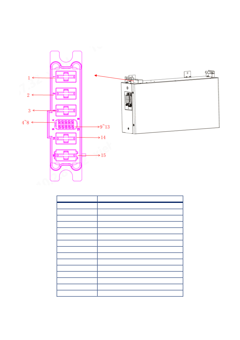
    Battery Pack Appearance
    BP48100PF1A-G2
    Power button
    DC SWITCH
    22

    Page 23

    Original PDF
    Battery port information
    3.7
    3.7.1
    Battery interface female
    Code
    Describe
    1
    2
    3
    4
    5
    6
    7
    8
    9
    10
    11
    12
    13
    14
    15
    Battery-
    Battery-
    Chassis ground
    CANH
    Activate_5V+
    Inverter_key+
    Inveter_Contact+
    UP_IN+
    CANL
    Activate_5V-
    Inverter_key-
    Inveter_Contact-
    UP_IN-
    Battery+
    Battery+
    23

    Page 24

    Original PDF
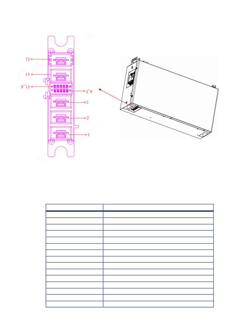
    3.7.2
    Battery interface male
    Figure 3-4 Appearance of BP48100PF1A-G2
    Code
    Describe
    1
    2
    3
    4
    5
    6
    7
    8
    9
    10
    11
    12
    13
    14
    15
    Battery-
    Battery-
    Chassic ground
    CANH
    Activate_5V+
    NC
    NC
    DO_OP+
    CANL
    Activate_5V-
    NC
    NC
    DO_OP-
    Battery+
    Battery+
    24

    Page 25

    Original PDF
    3.8
    Energy Management System (EMS)
    The inverter incorporates an electric energy management system (EMS) for low- voltage power distribution systems. It is an extended development of the energy management system that complies with the standard specifications of the power distribution system. It is highly automated, easy-to-use, high-performance, and highly reliable. You can turn on Bluetooth or WIFI switch on your mobile phone and then open the Green Hero APP to deploy loads, optimize operation, and effectively save power.
    3.9
    Parallel System
    With the INF-4-0/INF-5-0/INF-6-0/INF-8-0/INF-10-0/INF-10-0-BE/INF-12-0, you can connect up to four inverters of the same model in parallel. Connect the loads in parallel on both the grid and BACK UP sides. A parallel system increases capacity. One E10KT-D22 has a rated output of 10 kW on the grid side. Three E10KT-D22 units in parallel provide 30 kW (= 3 × 10 kW). Calculate the rated output on the BACK UP side in the same way.
    To build a parallel system, you must set one inverter as the primary inverter, and others as subordinate inverters. For more information, see Installing a Parallel System.
    NOTE
    • In a parallel system, the total grid power and total load power of each inverter
    can be viewed through the Green Hero APP on a mobile device.
    • In a parallel system, for some settings, such as working mode, zero export,
    and time setting of the PEAK SHIFT mode, you only need to set them in the primary inverter. These settings in the subordinate inverters are to be forced to synchronize with the primary inverter, but the setting values shown on the Green Hero APP of the subordinate inverters do not automatically change in synchronization.
    • In a parallel system, all settings must be the same for all inverters except for the
    addresses of the inverters.
    3.10
    Scenarios
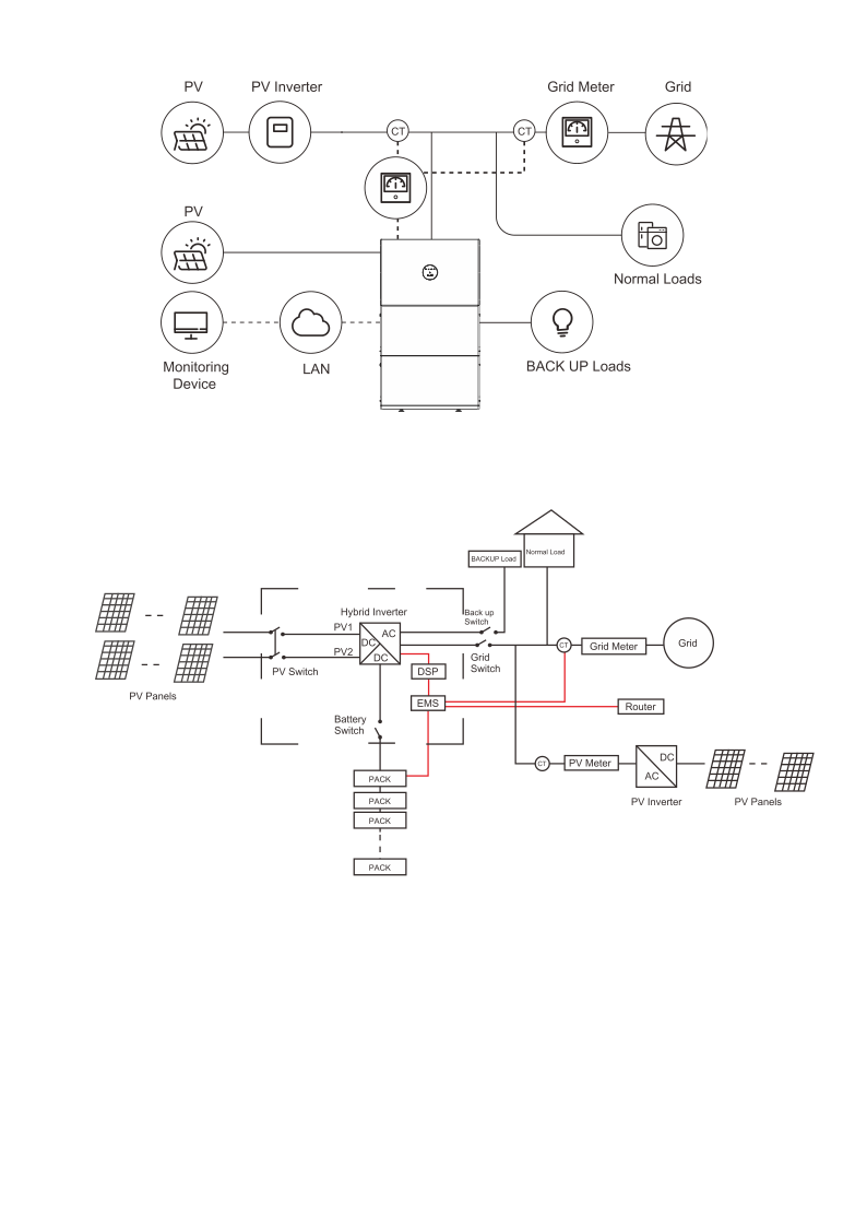
    The INF-4-0/INF-5-0/INF-6-0/INF-8-0/INF-10-0/INF-10-0-BE/INF-12-0 can be used in both a DC-coupling system and an AC- coupling system.
    3.10.1
    DC-coupling System
    25

    Page 26

    Original PDF
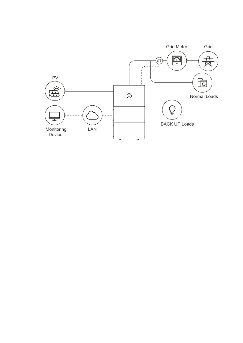
    In a DC-coupling system, the DC electricity generated by the PV panels is directly sent to and stored in the batteries through the inverter. A DC-coupling system is ideal for a new on- and off-grid solar+ storage system installation.
    Figure 3-5 DC-coupling System
    26
    GridNormal Loads

    Page 27

    Original PDF
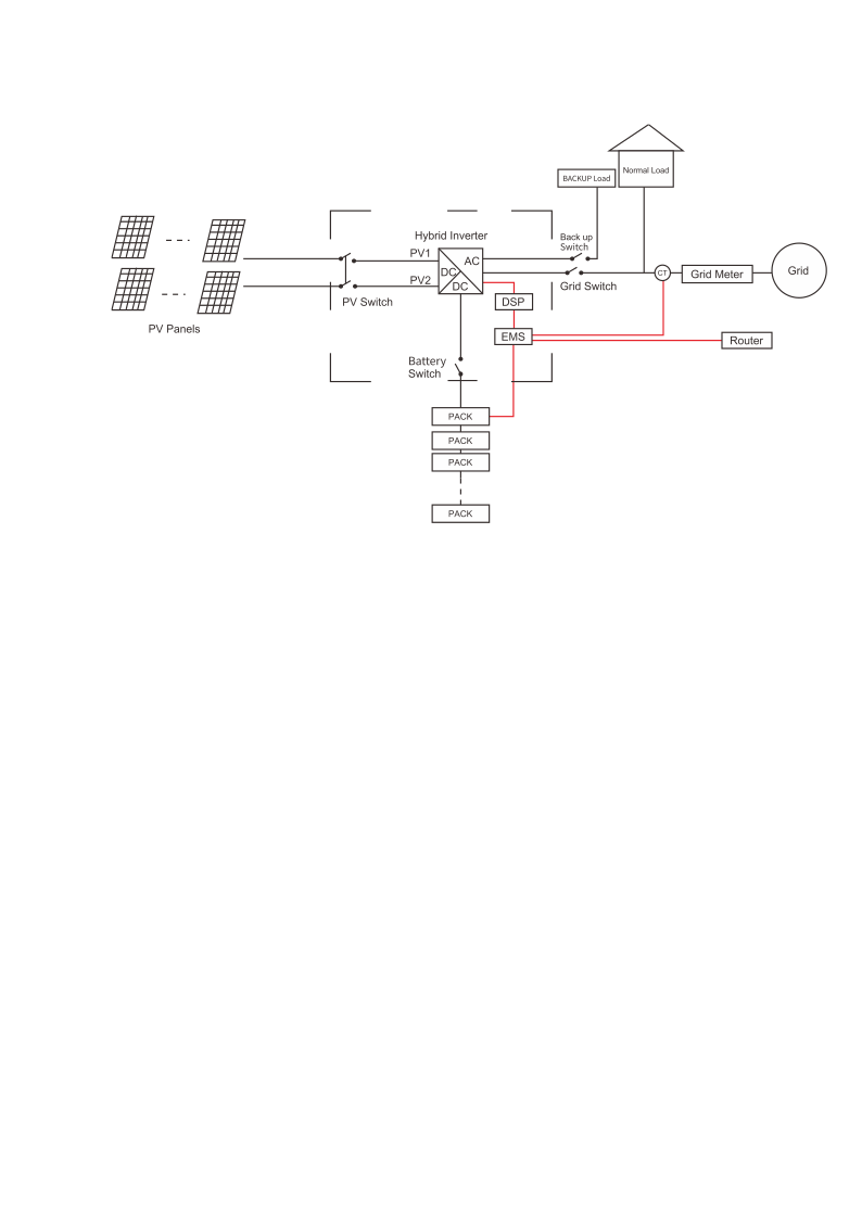
    Here is the single line diagram of a DC-coupling system.
    Figure 3-6 Single Line Diagram, DC-coupling System
    3.10.2
    AC-coupling System
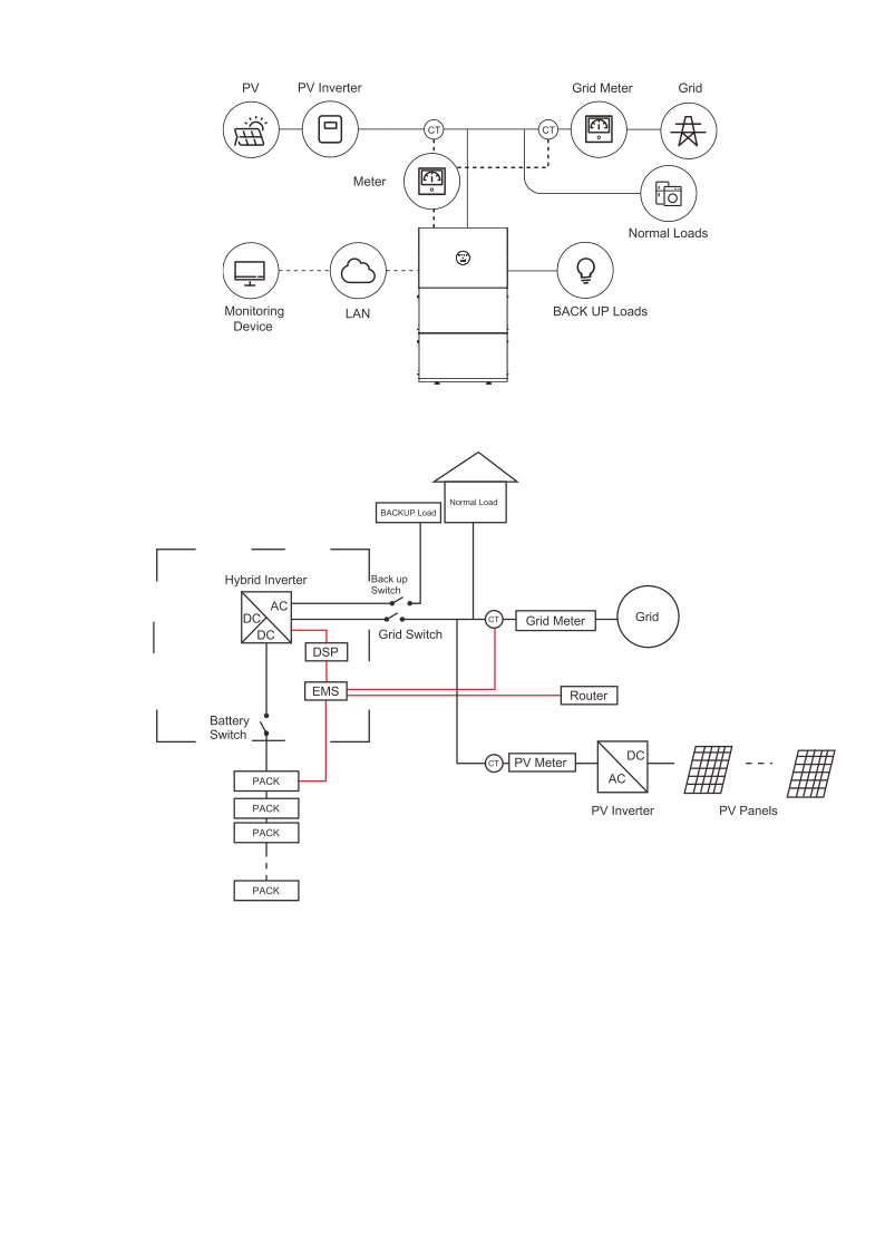
    In an AC-coupling system, DC electricity flows from PV panels to the inverter, the AC electricity from the inverter flows to the household loads or other inverters to transform the AC electricity back to DC electricity, and then store it in the batteries. An AC-coupling system is ideal for retrofit.
    The INF-4-0/INF-5-0/INF-6-0/INF-8-0/INF-10-0/INF-10-0-BE/INF-12-0 supports two AC- coupling system schemas.
    If you already have a PV inverter and now want to add an energy storage system to the inverter, but no PV panel is available for connection, you can use AC- coupling system Schema 1.
    When the photovoltaic array is exposed to light, it supplies a d.c. voltage to the PCE.
    27
    Normal LoadBACKUP LoadHybrid InverterGrid SwitchGrid MeterGridPV SwitchPV Panels

    Page 28

    Original PDF
    Figure 3-7 Ac-coupling System, Schema 1
    Figure 3-8 Single Line Diagram, AC-coupling System Schema 1
    If you already have a PV inverter, now want to add an energy storage system to the inverter, and a PV panel is available for connection, you can use Schema 2 of AC-coupling system.
    28
    PV InverterGrid MeterGridNormal LoadsBACK UP LoadsNormal LoadBACKUP LoadHybrid InverterGrid SwitchGrid MeterGridPV InverterPV Panels

    Page 29

    Original PDF
    Figure 3-9 AC-coupling System, Schema 2
    Here is the single line diagram of an AC-coupling system Schema 2.
    Figure 3-10 Single Line Diagram, AC-coupling System Schema 2
    29
    PV InverterGrid MeterGridBACK UP LoadsPV PanelsPV SwitchHybrid InverterBACKUP LoadGridGrid MeterPV InverterGridPV Panels

    Page 30

    Original PDF
    3.11
    Wiring Diagram
    Supported Grid Types
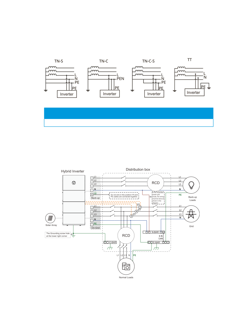
    For the gird structure with N cable, the effective value of the voltage between the neutral wire and the ground wire must be less than 10V.
    NOTICE
    Make sure that the grounding resistance is less than 10 Ω.
    In Australia, New Zealand, and South Africa, direct connection of the N cable and the PE cable in the distribution box is necessary, as shown in Figure 3-11
    Back-up:4-6KW 32A;8-12KW 40A;
    On-grid:4-6KW 40A;8-12KW 63A;
    Figure 3-11 Wiring for Australia, New Zealand, and South Africa
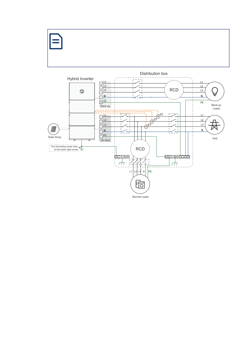
    Outside Australia, New Zealand, and South Africa, the N cable and the PE cable in the distribution box must be wired separately, as shown in Figure 3-12.
    30
    Distribution boxHybrid InverterSolar ArrayGridNormal Loads

    Page 31

    Original PDF
    NOTE
    Make sure that the grounding of the BACK UP load is correct and tightened. Otherwise, during a grid failure, the BACK UP may not function normally.
    Figure 3-12 Wiring Outside Australia, New Zealand, and South Africa
    The battery power and signal connectors are in blind-inserted mode, so the communication was automatically connected after the battery packs and the inverter were assemble.
    31
    Distribution boxSolar ArrayGridNormal Loads

    Page 32

    Original PDF
    3.12
    System States
    3.12.1
    Inverter States
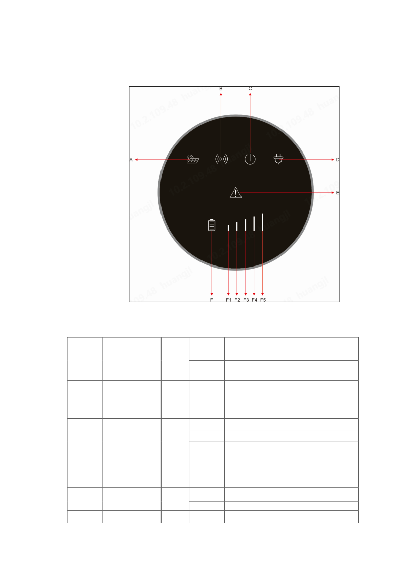
    The inverter can be in six states shown in Table 3-2.
    Table 3-2 Inverter States
    Icons
    Implication
    Color
    Status
    Describe
    On
    Flashing
    Off
    PV operating normally
    PV connected but not operating
    PV not connected
    Monitoring backend connected and
    communication normal
    Monitoring module not connected or
    communication abnormal
    A
    PV Indicator
    Green
    On
    Communication
    Indicator
    B
    Green
    Off
    On
    System in On-grid operation mode
    Flashing
    System in bypass mode
    System in initialization, standby, off-
    grid, fault, commissioning, or upgrade
    mode
    System in off-grid PV charging mode
    PV off-grid charging not in progress
    C
    Grid Indicator
    Green
    Off
    D
    On Off
    Off
    Off-Grid Indicator
    Indicator
    Green
    On
    System fault
    E
    Fault Indicator
    Red
    Off On
    On
    F
    Green
    Battery operating normally
    32

    Page 33

    Original PDF
    Battery abnormal (alarm or BMS
    communication abnormal)
    Battery shutdown or battery
    disconnected
    ≥80%
    Flashing
    Battery
    Indicator
    Off
    F5:5/5
    ≥60%
    F4:4/5
    Battery SOC
    Indicator
    (Flashing
    during
    charging)
    ≥40%
    F3:3/5
    F
    Green
    ≥20%
    F2:2/5
    ≥5%
    F1:1/5
    0
    <5%
    NOTE
    For more information about the error codes, see Error Codes of the System and Alarm Codes of the System.
    3.12.2
    Battery Pack States
    A battery pack can be in five states: OFF, NORMAL, ALARM, FAULT, and PROTECTION. For more information, see Indicator Lights and States.
    3.13
    Working Modes
    The INF-4-0/INF-5-0/INF-6-0/INF-8-0/INF-10-0/INF-10-0-BE/INF-12-0 supports three working modes: SELF CONSUME, BAT PRIORITY, and PEAK SHIFT. You can choose a working mode through the integrated EMS. For more information, see the WORK MODE subsection under Scene setting.
    3.13.1
    SELF CONSUME
    In SELF CONSUME mode, the electricity generated by the PV panels is consumed in this order:
    Step 1. Supplies electricity for household use.
    Step 2. Stores the excess electricity in batteries.
    Step 3. Pushes the excess electricity onto the local power grid.
    When the sun goes down, the household power supply is automatically switched to the batteries. If the power supply from the batteries is not sufficient, power is sourced from the local power grid.
    3.13.2
    PRIORITY
    In BAT PRIORITY mode, the batteries are only used as BACK UP. When the grid fails, the household load is powered by the batteries. When the grid is working, the household load is powered by the grid, not by the batteries. The PV panels or the
    33

    Page 34

    Original PDF
    local power grid send electricity to the batteries, where it is stored until needed.
    3.13.3
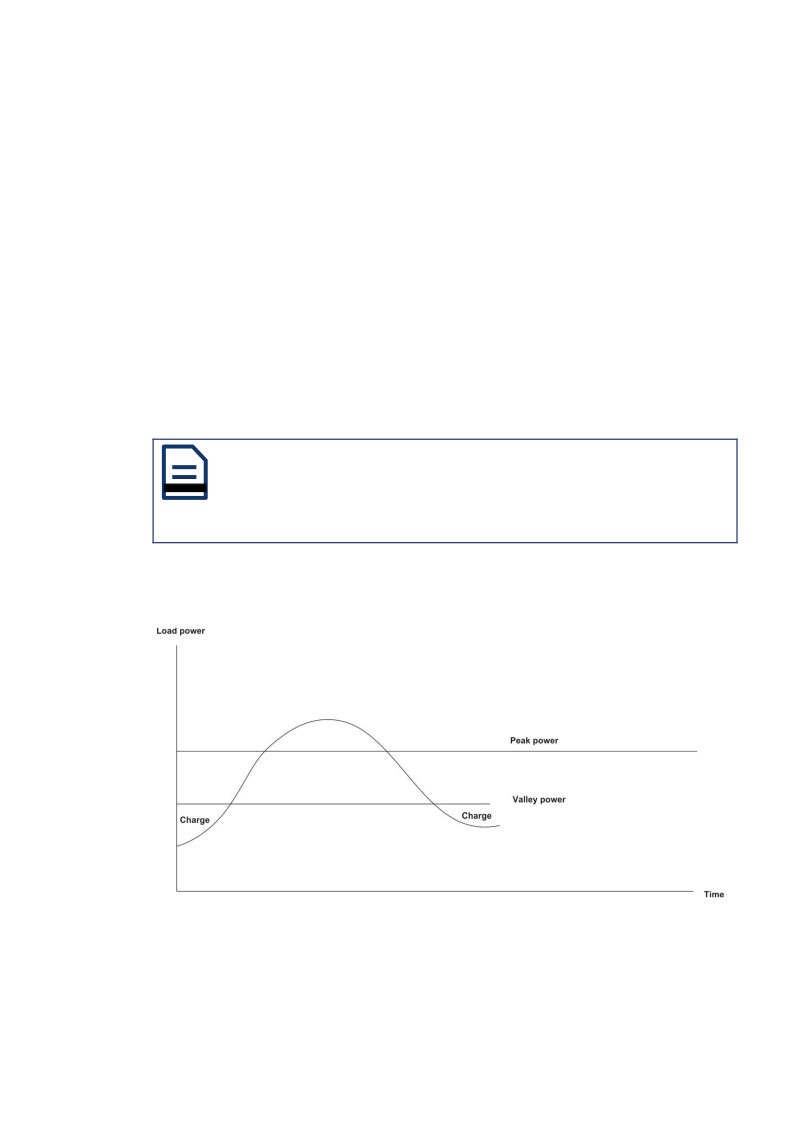
    PEAK SHIFT
    In PEAK SHIFT mode, you can determine the charging and discharging time of the battery yourself ,and if you enabling the peak shift power control, you can set the peak power and valley power of the load power.
    4
    Installation
    With the INF-4-0/INF-5-0/INF-6-0/INF-8-0/INF-10-0/INF-10-0-BE/INF-12-0 , you can install a PV energy storage system using either of two schemas:
    • Install one hybrid inverter and 1~8 battery packs.
    • Install a parallel system with multiple hybrid inverters of the same model, each
    with its own battery packs, connected in parallel. For more information, see Installing a Parallel System.
    Follow the steps in Figure 4-1 to install a PV energy storage system with an INF-4- 0/INF-5-0/INF-6-0/INF-8-0/INF-10-0/INF-10-0-BE/INF-12-0 .
    Prepare tools and instruments
    Choose installation position
    Check package
    Start
    Connect DRED
    Mount inverter
    Mount battery packs
    Connect generator
    Connect inverter and PV panels
    Connect batteries
    End
    Optional
    Connect data logger
    Connect CT or smart meter
    Connect AC cables
    Install system
    Figure 4-1 Installation Procedure
    DANGER
    Only trained professionals are permitted to install the system. Four trained professionals are necessary to carry out installation.
    4.1
    Checking the Package
    Open the package, make an inventory of its contents, and make sure that all hybrid inverter and battery pack components are present.
    WARNING
    Before opening the package, make sure that the box is not damaged.
    34

    Page 35

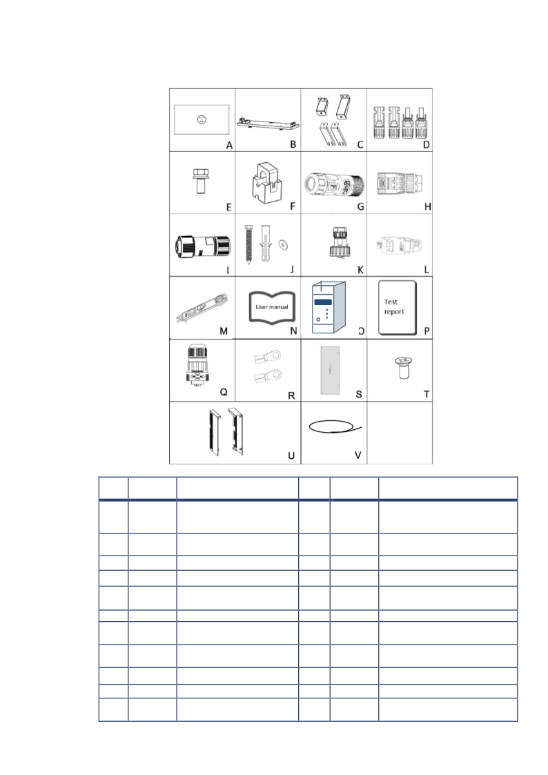
    Original PDF
    4.1.1
    Hybrid Inverter Components
    Quantity
    Description
    Item
    Quantity
    Description
    Item
    Base (must be removed from
    inverter bottom immediately
    after unpacking)
    PV terminals: 2 positive,
    2 negative
    CT (optional)
    Inverter (packed and assembled with base)
    A
    1
    B
    1
    C
    4
    Mounting bracket
    D
    2
    E
    8 sets
    M4x12 Bolt
    F
    3
    G
    1
    AC BACK UP connector
    H
    1
    AC grid connector
    2 screws, 2 rubber sleeves,
    2 gaskets (base and wall bracket)
    WIFI+BLE+LAN Dongle
    User manual, Warranty card,
    Certificate of quality card
    I
    1
    WIFI Connector
    J
    1 set
    K
    3
    RJ45 Connector
    L
    1
    M
    1
    PV connector tool
    N
    1
    Smart Power Meter
    O
    1
    P
    1
    Test report
    Q
    2
    CT Connector
    R
    2
    OT terminals
    S
    1
    Positional Punch card
    T
    2
    Countersunk screw
    RS485 Communication Cable (10 m)
    U
    2
    Mechanical cover
    V
    1
    35

    Page 36

    Original PDF
    4.1.2
    Battery pack Components
    A battery pack delivery includes the following.
    Mechanical cover*2
    4.1.3
    Accessory (Optional)
    When 5 to 8 battery packs are used, additional accessories must be used in combination. For the specific connection method, please refer to the base installation diagram in Section 4.4.2.
    Floor Stand Support (Optional)
    Battery Top Cover(Optional)
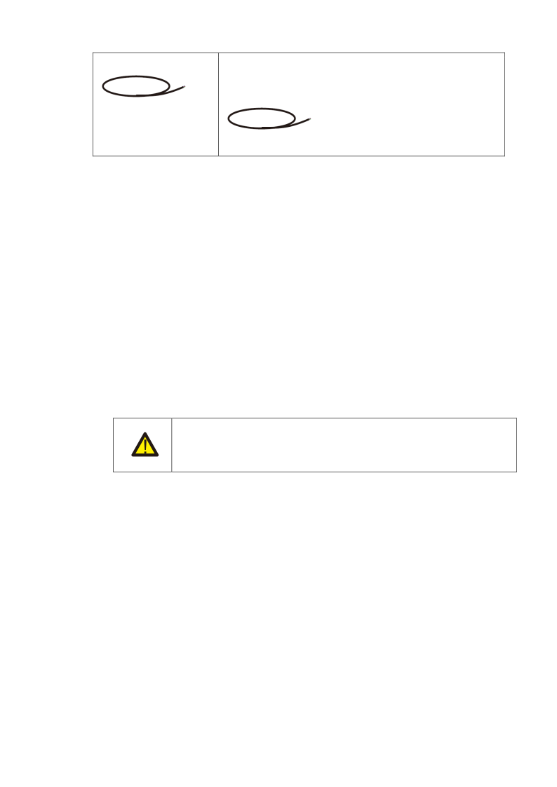
    Cable(Optional):
    1*Communication cable;Power cable(1*Black,1*Orange); 1*PE cable
    36

    Page 37

    Original PDF
    Torque wrench (M1.4/M2.5/M5/M6/M8)
    4–6 kW: 4–6 mm²)
    4.2
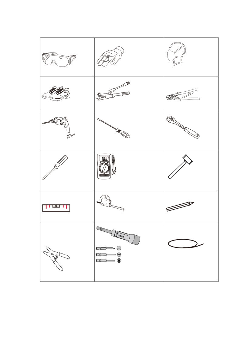
    Preparing Tools and Instruments
    Protective Goggles
    Protective Gloves
    Protective Mask
    Protective Shoes
    Wire Clamp
    Cable Crimper
    φ10mm Power Drill
    Flat-head Screwdriver
    Torque Wrench
    Cross Screwdriver
    Multi-meter
    Rubber Mallet
    Leveling Instrument
    Tape Measure
    Marker Pen
    O N GRID Wire
    (8~12KW:6mm 2 ;
    Wire Stripper
    37

    Page 38

    Original PDF
    BACK UP Wire
    (8~12KW:4mm 2 ;
    4~6KW :2.5~4mm 2 )
    PV wire (4 mm², max. voltage 1,000 V)
    4.3
    Installation Position Requirements
    The INF-4-0/INF-5-0/INF-6-0/INF-8-0/INF-10-0/INF-10-0-BE/INF-12-0 energy storage system can be installed indoors or outdoors, but the position for installation must meet these requirements:
    • Sufficient space for personnel to install and maintain the equipment and to
    Observe the LED indicator light status on the hybrid inverter.
    • Ambient temperature: For the inverter and battery pack. See Specifications.
    • Relative humidity: 0~95% (No condensation).
    • Level floor, but not sloped.
    • Sheltered from direct sunlight or severe weather.
    • Well ventilated.
    • NOT near flammable or explosive materials.
    • NOT exposed to salt hazards.
    • NOT subject to strong vibration or electromagnetic fields.
    • NOT a habitable room, as defined in AS/NZS 3000.
    • NOT accessible to children.
    The energy storage system needs to keep a certain safe distance (>1m) from the surrounding doors, windows, escape routes and other systems.
    4.3.1
    Restrictions
    DO NOT install the system in these locations:
    • Habitable rooms, as defined in AS/NZS 3000.
    • A ceiling or wall with a cavity.
    • On a roof.
    • Entrance or exit.
    • Underneath staircases or passageways.
    • Areas where relative humidity and condensation exceed 95%.
    • Places exposed to salty air.
    • Earthquake zones, unless additional safety measures have been taken.
    • Places more than 4,000 meters above sea level.
    • Places in direct sunlight or places where the ambient temperature varies a lot.
    • Places with flammable materials and gases.
    • Places where explosions may occur.
    • Locations where the installation of panels is restricted by AS/NZS 3000.
    • Within 600 mm of any heat source, for example, hot water unit, gas heater, air
    38

    Page 39

    Original PDF
    conditioning unit, or any other equipment.
    • Within 600 mm of any outlet.
    • Within 600 mm of any window or vent.
    • Within 600 mm of the side of any other installation.
    • Hazardous areas with insufficient distance from gas cylinders or gas relief valves as
    defined in AS/NZS 3000. When the INF-4-0/INF-5-0/INF-6-0/INF-8-0/INF-10-0/INF-10-0-
    BE/INF-12-0 is installed indoors, make sure that the building structure, room furniture, and appliances do not interfere with the operation and maintenance of the system.
    If the INF-4-0/INF-5-0/INF-6-0/INF-8-0/INF-10-0/INF-10-0-BE/INF-12-0 is installed in a corridor, aisle, lobby, or similar area that leads to an emergency exit, at least one meter of space must be allowed for safe egress.
    To prevent fire, the wall or structural surface on which the INF-4-0/INF-5-0/INF-6- 0/INF-8-0/INF-10-0/INF-10-0-BE/INF-12-0 is mounted must be made of non- combustible material. If the wall or structural surface is not made of non- combustible material, a layer of non-combustible material can be placed between the equipment and the surface.
    4.3.2
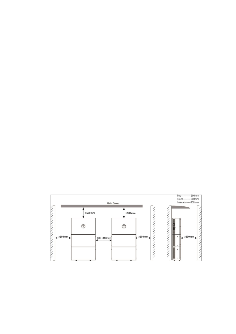
    Clearance Requirements
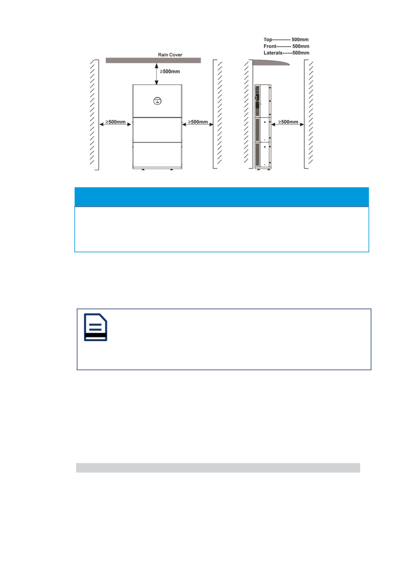
    If the INF-4-0/INF-5-0/INF-6-0/INF-8-0/INF-10-0/INF-10-0-BE/INF-12-0 is mounted on a wall or on a surface that is 300 mm from a wall or structure that separates the equipment from habitable rooms, the distance between the equipment and other structures or objects must be increased. The minimum required clearance is as follows:
    • 500 mm to the sides of the equipment.
    • 500 mm above the equipment.
    • 500 mm in front of the equipment.
    39
    Rain CoverTop--... 500mmFront-..... 500mmSides 500 mm

    Page 40

    Original PDF
    Figure 4-2 Peripheral Clearance Requirements for Installation
    NOTICE
    • For outdoor installations, a shelter above the equipment is necessary.
    • When installing the INF-4-0/INF-5-0/INF-6-0/INF-8-0/INF-10-0/INF-10-0-BE/INF-12-
    0 , make sure that the distance between the highest point of the equipment and the ground or the mounting platform does not exceed 2.2 meters.
    If the distance between the INF-4-0/INF-5-0/INF-6-0/INF-8-0/INF-10-0/INF-10-0- BE/INF-12-0 and the object above it, for example, a ceiling, is less than 500 mm, the surface of the object must be paved with non-combustible material in the form of a circle with a radius of 600 mm around the center of the equipment.
    NOTE
    The distance between the INF-4-0/INF-5-0/INF-6-0/INF-8-0/INF-10-0/INF-10-0-BE/INF-12-0 and the object above it must be more than 200 mm.
    4.4
    Installing the System
    Follow the steps in this section to install an INF-4-0/INF-5-0/INF-6-0/INF-8-0/INF-10-0/INF-10-0-BE/INF-12-0 energy storage system with one hybrid inverter.
    4.4.1
    Mounting the All in one system
    NOTES
    The inverter should be moved by four persons. One inverter weighs approximately 50 kg.
    Wear protective goggles and a mask to prevent the dust created during drilling from entering the respiratory tract and eyes.
    40
    Rain CoverFront-...••- 500mmSides 500 mm

    Page 41

    Original PDF
    PROCEDURE
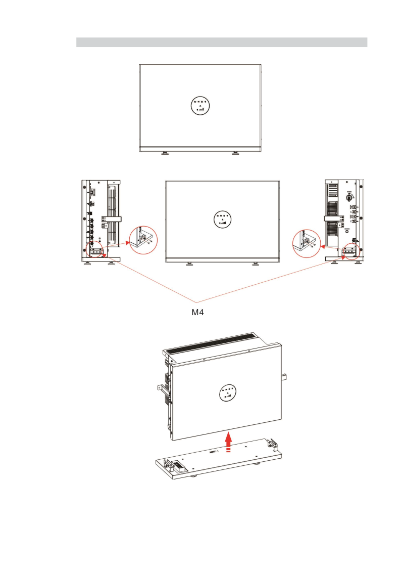
    Step 1. Remove the inverter from the carton.
    Step 2.
    Remove the fixing screws on the top and bottom of both sides (torque: 2 N.M). Note: The two screws on the top can be hand-tightened.
    Step 3. Remove the floor stand support.
    Step 4. Place the floor stand support horizontally on the ground.
    41

    Page 42

    Original PDF
    Step 5. Battery Pack Installation
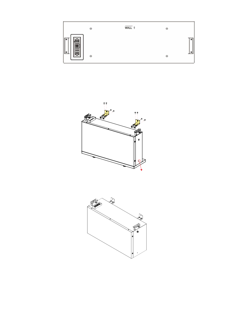
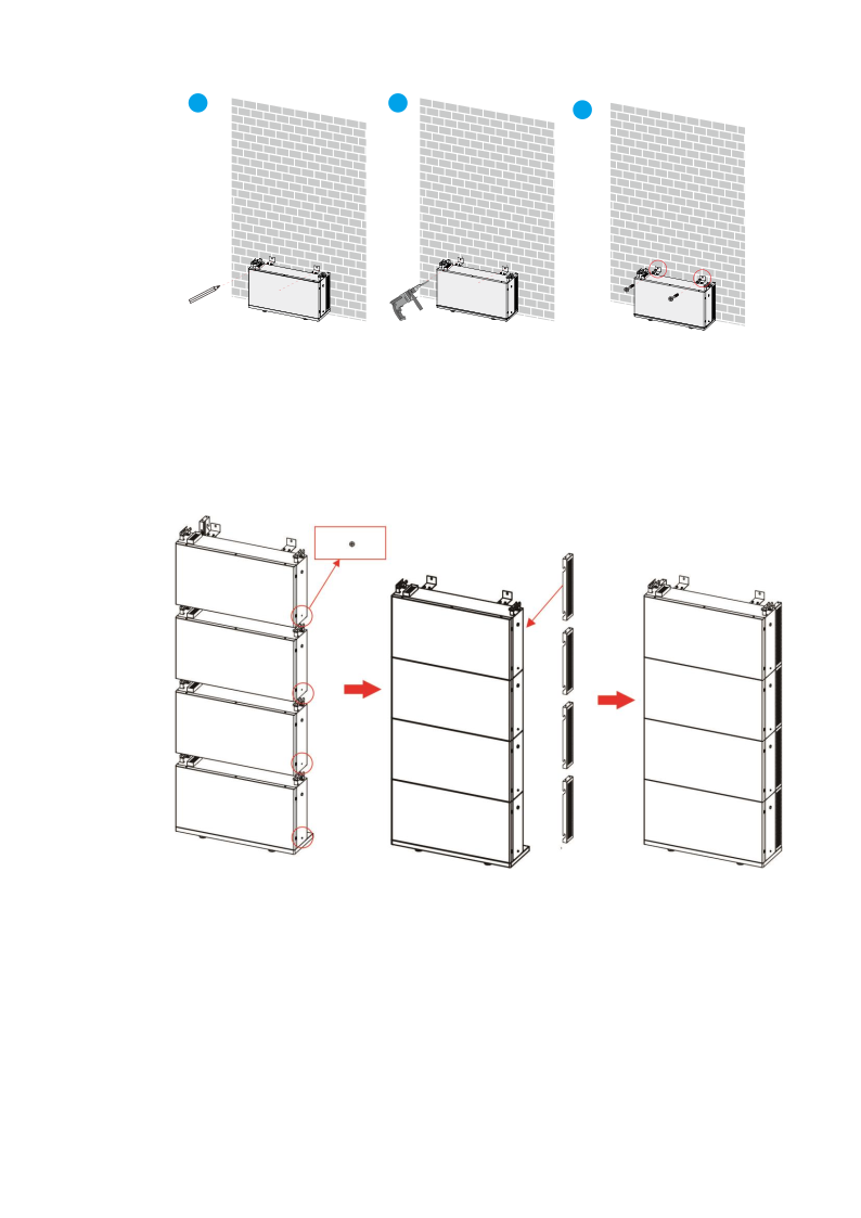
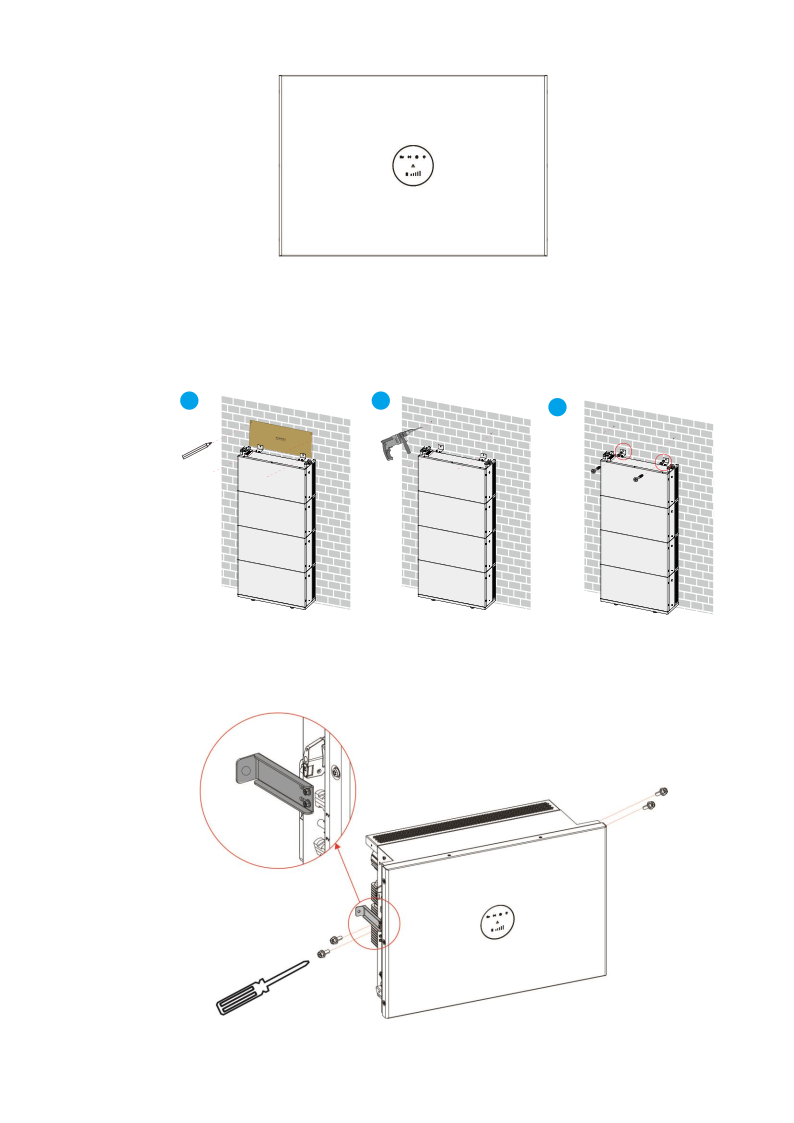
    5-1 Take the battery pack out of the carton and stand it up right on the base. First, screw the mounting kit-battery onto the battery pack, Then fix the mounting kit wall to the mounting kit battery with screws. Finally, place the battery pack close to the wall for marking, drilling, installing expansion tubes and screws.
    8 M5×12 screws
    M4×12 screws
    4.3U battery pack:
    42

    Page 43

    Original PDF
    1
    2
    3
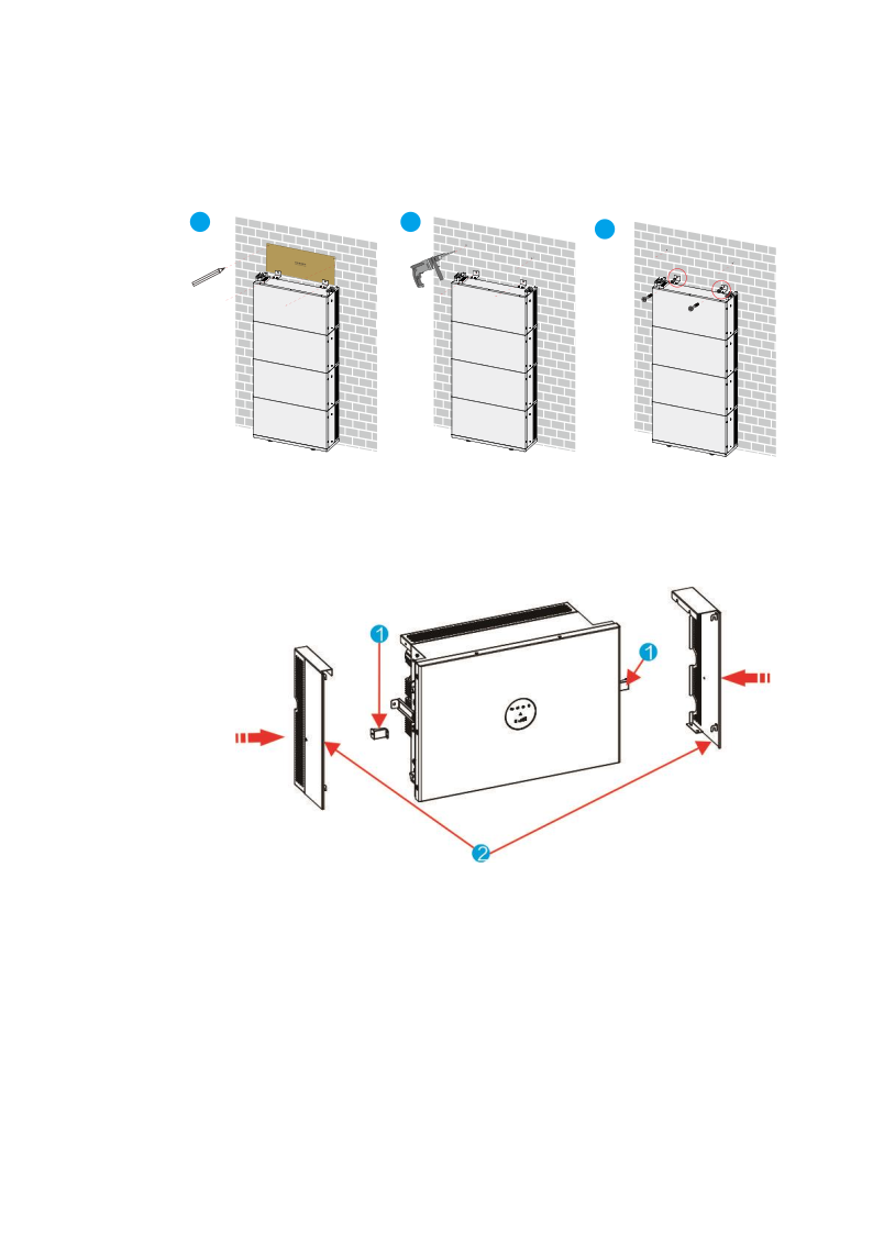
    5-2 Install a set of batteries and tighten the screws on both sides at the same time, then continue to stack the next battery module.
    Use M4*12 screws to tighten, the screw torque is 2.0N·M When needing to assemble the second battery (and all others), repeat step 5-1 to carry out the installation.
    After stacking the battery packs, install mechanical cover on both sides.
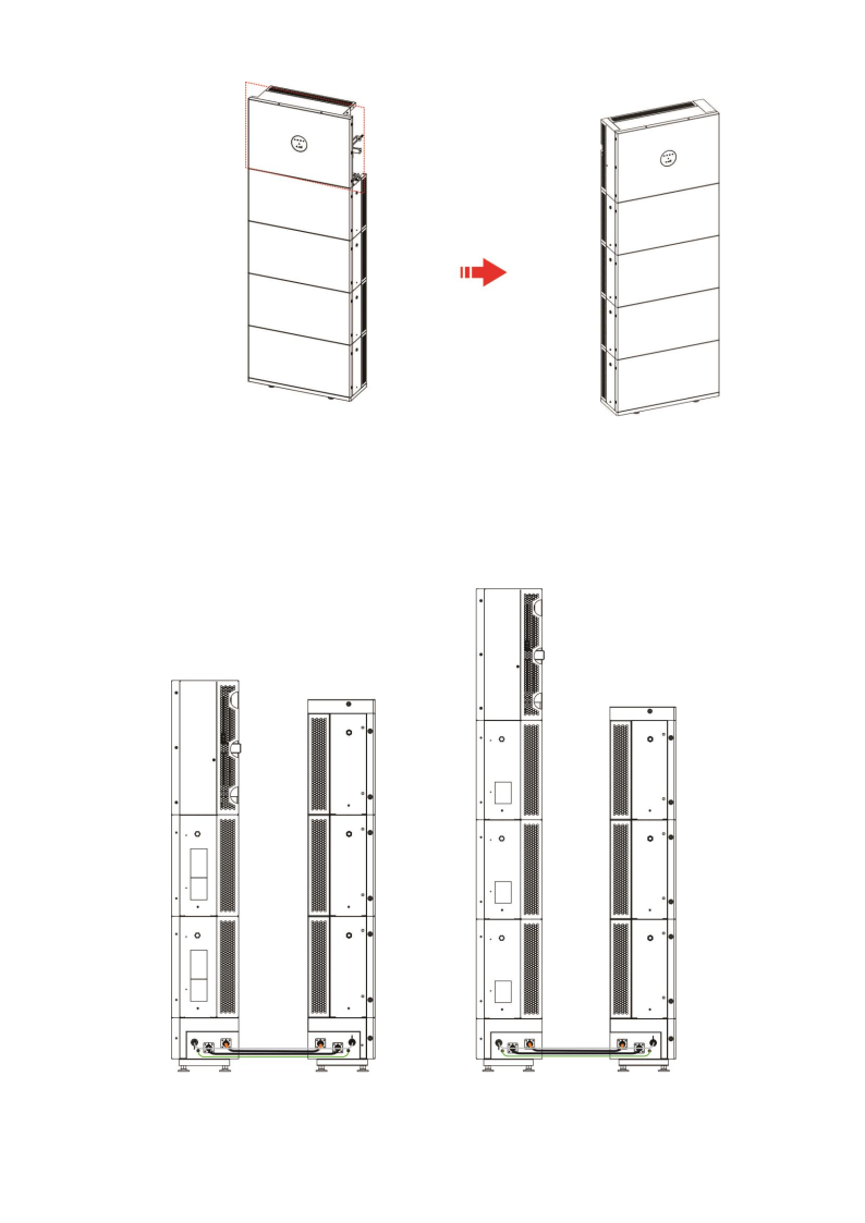
    Step 6.Install the hybrid inverter
    6-1 The disassembled inverter is shown in Figure 2.1.
    43

    Page 44

    Original PDF
    Figure 2.1
    6-2 Use the Positional Punch card to align the holes on the battery pack, mark the inverter mounting hole positions, and drill using a 10mm drill bit. The drilling depth should exceed 50mm. Place the expansion plug into the hole, then secure the base using ST6.3*50mm screws with a torque of 3.0 N·m.
    1
    2
    3
    Step 7. Install the lock wall bracket.
    Fix the mounting brackets on both sides of the inverter with screws.
    44

    Page 45

    Original PDF
    7-1 Stack the inverter on top of the battery pack and secure it using M4*12 screws (fasten into the upper screw holes) with screw a torque of 2.0 N·m.
    7-2 Install and secure the wall bracket. After adjusting the wall bracket, fix it using M4*12 screws with a screw torque of 2.0 N·m.
    1
    2
    3
    Step 8.Wiring harness installation reference, section 4.4.4
    Step 9.Install the side cover. Install the side covers on both sides of the inverter and tighten the screws.
    45

    Page 46

    Original PDF
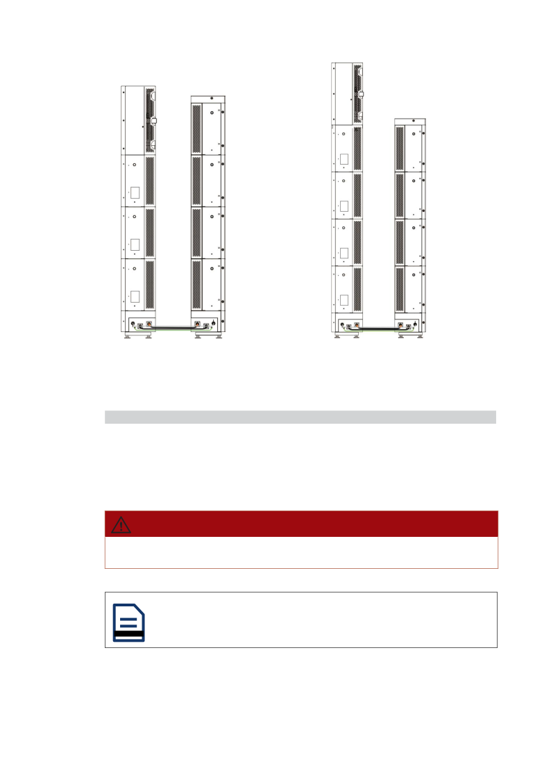
    4.4.2
    Connecting Battery Packs
    The battery power and signal connectors are in blind-inserted mode, so the communication was automatically connected after the battery packs and the inverter were assembled.
    Connect Five Battery Packs
    Connect Six Battery Packs
    46

    Page 47

    Original PDF
    Connect Seven Battery Packs
    Connect Eight Battery Packs
    4.4.3
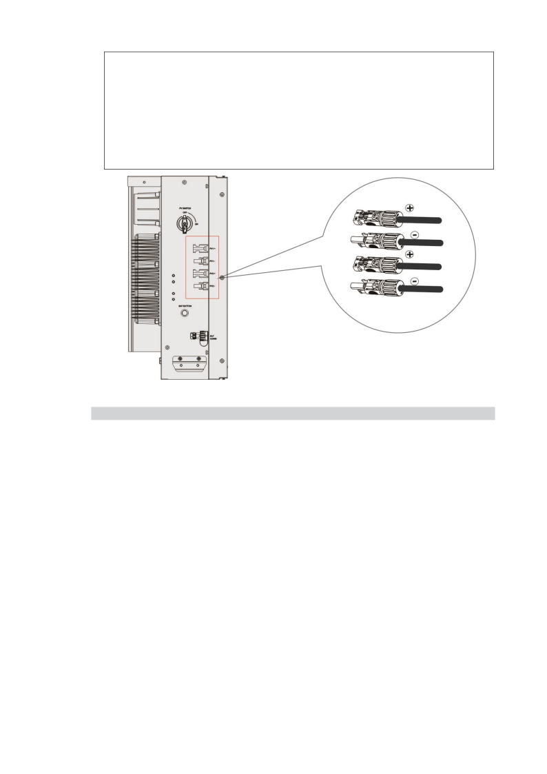
    Connecting the Inverter and PV Solar Panels
    NOTES
    •
    4mm2 PV wires are recommended for connection.
    •
    Distinguish the PV polarities and DO NOT reverse the connection.
    •
    Make sure that the input voltage of the PV is within the acceptable input voltage range of the inverter, not higher than 1000 V.
    DANGER
    Make sure that both the PV Switch inside the cable box and the switch on the PV solar panel are in the OFF position.
    NOTE
    47

    Page 48

    Original PDF
    The scenario where two photovoltaic strings are connected to a single power module requires the model and quantity configuration of the two photovoltaic strings to be consistent. The PV strings should not be grounded to ensure the minimum insulation resistance of the equipment. Before connecting the PV strings to the inverter, the minimum insulation resistance of the PV strings to ground must meet the requirement (R = maximum input voltage / 30mA). If the insulation resistance value is lower than the above requirement, it will trigger an insulation resistance inverter alarm (Low insulation impedance).
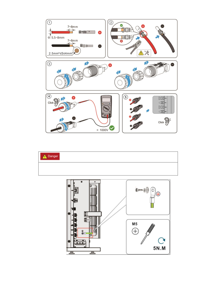
    PROCEDURE
    Step 1.
    Use a wire stripper to remove an approximately 8 mm length of insulation layer of the PV wire.
    Step 2.
    Then place the metal connector on top, and finally, use the crimping tool to crimp the meatal connector to the wire
    Step 3.
    After the metal conductor is crimped to the wire, you have to place the metal connector into the terminal cover, strain reliever and compression sleeve.
    Step 4.
    Finally, you plug the metal connector into the connector housing and screw all the components together using the assembly tool. Properly tightening MC4 solar connector ensures they are water-tight and safe to use. Use a multi-meter to measure the voltage of the PV wire. Make sure that the voltage is lower than 1000 V.
    Step 5.
    Plug the PV wires into the PV1+, PV1-, PV2+, and PV2- ports in the inverter and snap them.
    48
    Page 49

    Original PDF
    4.4.4
    Install the earth cable
    Precautions
    Please confirm that the PE cable is reliably connected. If it is not connected or loose, it may cause electric shock hazard.
    PE cable: 4~6mm 2
    Figure Installation of PE cable
    49
    ClickClickDANGER

    Page 50

    Original PDF
    4.4.5
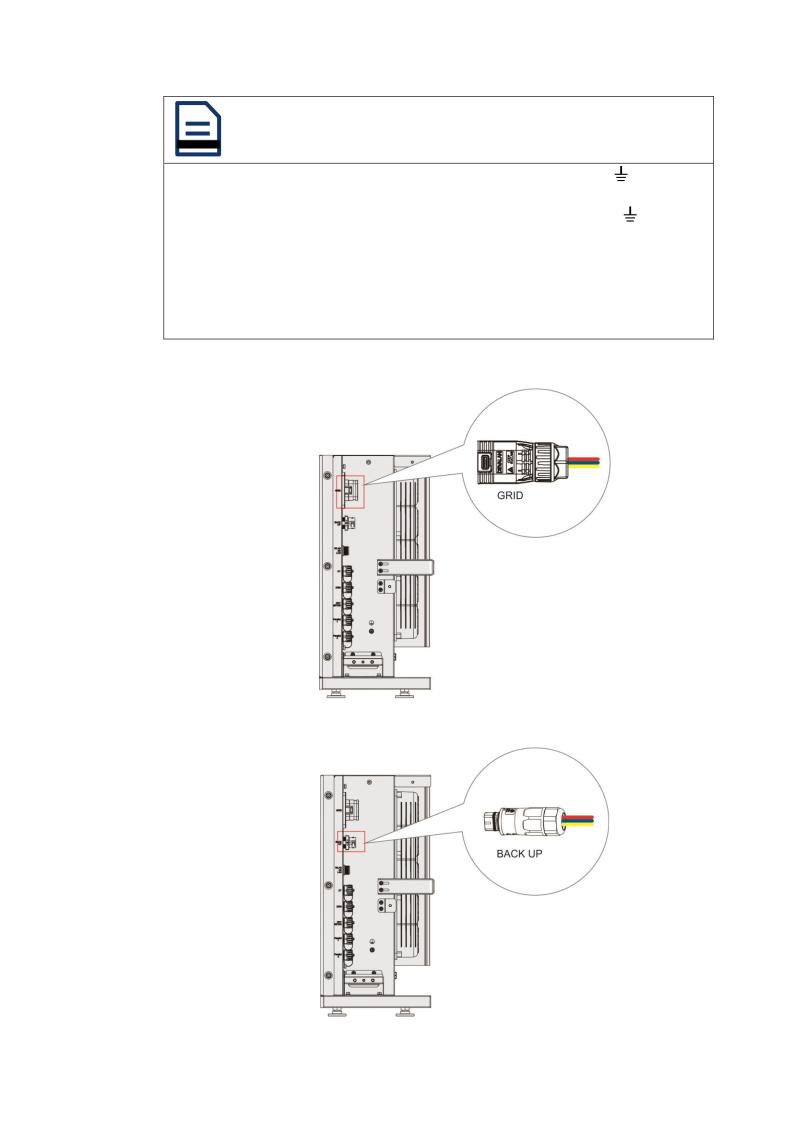
    Connecting to Grid and Loads
    NOTE
    There are five connection ports marked “L1, L2, L3”, “N”, and the grounding symbol () inside the AC connector. The live wire should be connected to the “L” terminal, the neutral wire to the “N” terminal, and the ground wire to the terminal marked with the grounding symbol (). The L and N wires of the AC cable must not be reversed or short-circuited. The PE wire of the AC cable must be grounded. The connector cable only supports multi-strand copper wires, and requires riveted tube/pin type terminals. The terminal specifications are selected according to the wire gauge.
    GRID:
    BACK UP:
    50

    Page 51

    Original PDF
    NOTICE
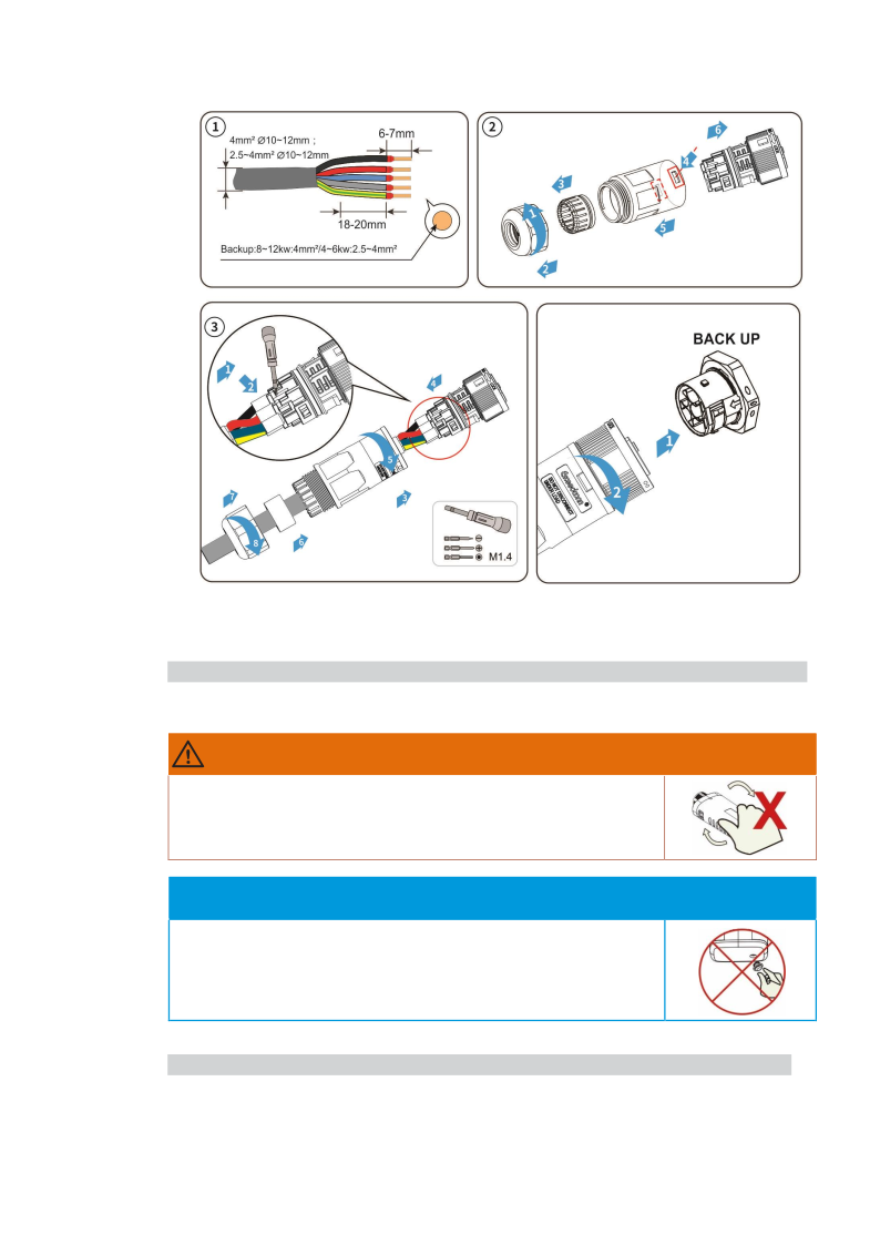
    • Recommended for BACK UP: 4 mm² (8–12 kW) or 2.5–4 mm² (4–6 kW).
    Recommended for ON GRID: 6 mm² (8–12 kW) or 4–6 mm² (4–6 kW).
    • Make sure that the resistance of the wires is lower than 1 Ω.
    • Make sure that the grounding resistance, measured between the inverter case
    and the earth terminal of the distribution box, is less than 10 Ω.
    DANGER
    Before connection, make sure that the AC current breakers and the LOAD Switch in the distribution box are in the OFF state.
    CAUTION
    When connecting the wires to the connector, make sure that the phase wires and the earth wire are connected correctly.
    CAUTION
    Appliances such as air conditioners require sufficient time to equalize refrigerant gases within the circuit, so it takes at least two or three minutes to restart. If power supply is short-circuited and restored within a short period, it can cause damage to these appliances connected to the power supply. Before installing such appliances, make sure that the air conditioner has a time delay function to prevent such damage. In the absence of a time delay function, the inverter triggers an overload fault and cuts off the output to protect your appliances, but internal damage to appliances can sometimes still occur.
    NOTE
    The type A or B RCD (≥ 300 mA) must be installed on the BACK UP port of the system according to local regulations. An AC circuit breaker of these specifications is recommended:
    • For ON-GRID connection:
    4–6 kW: 40 A/400 VAC, 6 kA. 8–12 kW: 63 A/400 VAC, 6 kA.
    • For BACK UP connection:
    4–6 kW: 32 A/400 VAC, 6 kA. 8–12 kW: 40 A/400 VAC, 6 kA.
    PROCEDURE
    Step 1.
    Use a wire stripper to remove an appropriate length of the jacket and insulation layer from one wire of the AC cable.
    51

    Page 52

    Original PDF
    Step 2.
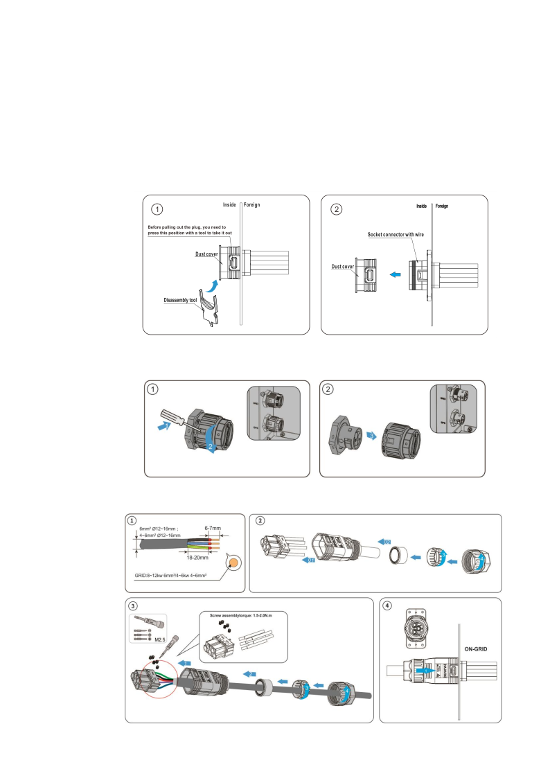
    Disassemble the grid/load connectors in the order shown in the diagram.
    Step 3.
    Unscrew the swivel nut from the threaded sleeve of the AC connector and Insert the wire into the corresponding pins of the AC connector and use a cross screwdriver No.1 (torque 0.8 N.M) to tighten the screws. Then assemble the AC connector components in the order shown in the diagram.
    Step 4.
    Disassembly and assembly of waterproof cover
    GRID: Use the unlocking tool to press the connector unlock,then pull
    BACK UP: rotate the locker according to the direction instructed by the
    marks on the locker.
    Step 5.
    Plug the AC connector into the ON GRID or BACK UP port inside the inverter and tighten the connector.
    52
    Dust coverSocket connector with wireDust coverBetore pulling out the plug, you need topress this position with a tool to take it outDisassembly tooGRID: 8–12 kW 6 mm² / 4–6 kW 4–6 mm²Screw assomblytorque: 1.5-2.0N.m

    Page 53

    Original PDF
    Figure ON GRID connector
    Figure BACK UP connector
    4.4.6
    Connecting a Wi-Fi LAN Dongle
    NOTES
    For more information, see Wi-Fi LAN Dongle Quick Guide.
    WARNING
    DO NOT hold the logger body to rotate while installing or removing the logger.
    NOTICE
    DO NOT remove waterproof plug.
    PROCEDURE
    Step 1. Plug the stick logger into the WLAN/4G/LAN port inside the cable box.
    53
    Backup:8~12kw:4mm2/4~6kw:2.5~4mm2

    Page 54

    Original PDF
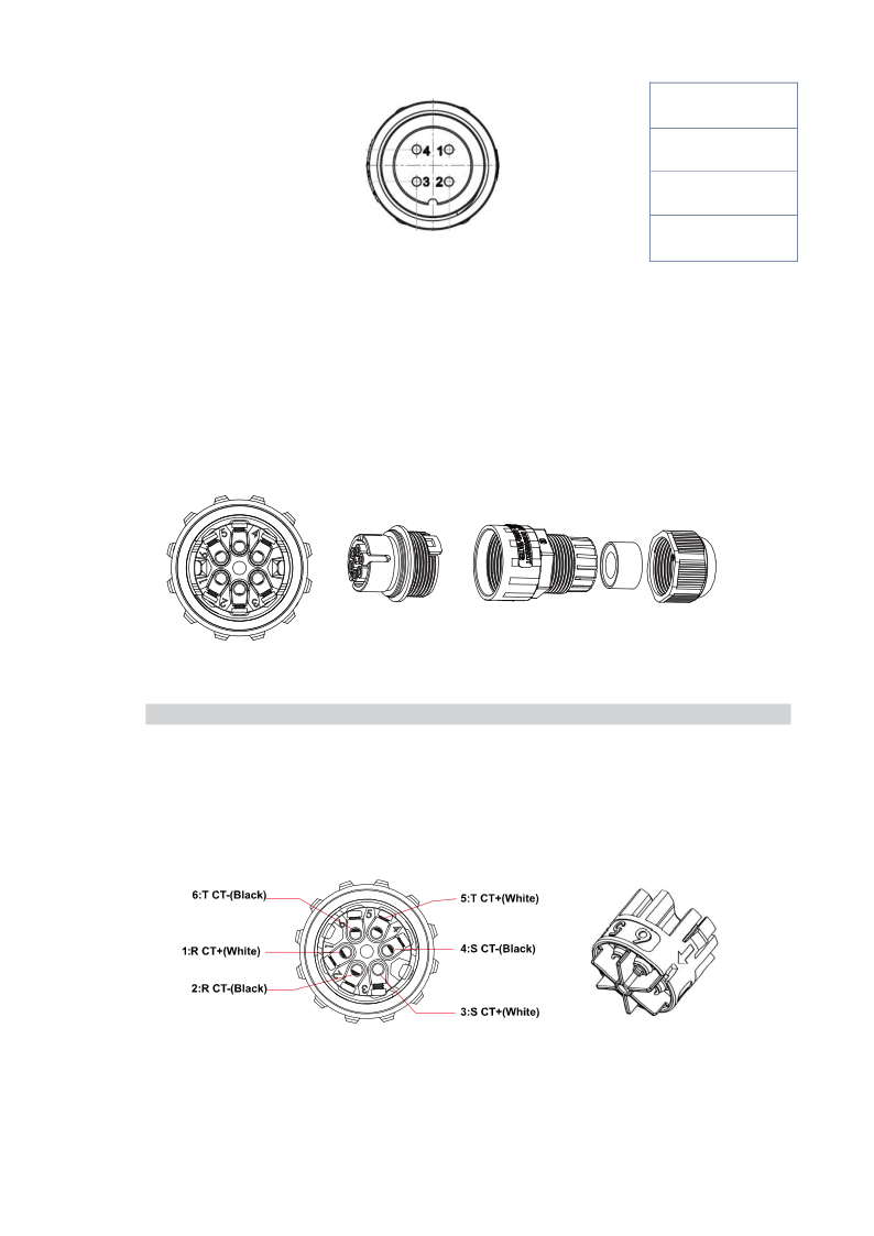
    Pin 1: +12V
    Pin 2: GND
    Pin 3: RS485-A
    Pin 4: RS485-B
    Figure 4-23 Pins of the WLAN/4G/LAN Port
    4.4.7 Connecting External CT
    You must connect external CT or a smart grid meter between the inverter and the power grid.
    If you want to connect a smart meter, see Connecting a Smart Meter.
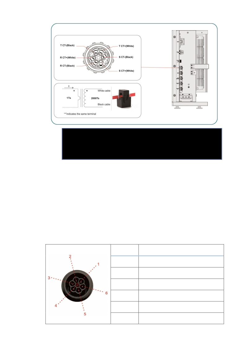
    If you want to connect external CT, one CT and a CT connector are necessary. The connector has six pins, as shown in Figure 4-24. For more information, see Step 2 in the procedure.
    Figure 4-24 Pins of CT Connector
    NOTES
    The external CT must be mounted near the power grid side. If the CT test passes but the inverter output power is not acceptable, for example, power cannot be controlled or output power is always 0 W, check the position where the CT are mounted.
    Table 4-3 Pin Description of CT Port
    54
    6:T CT-(Black)5:T CT+(White)1:R CT+(White)2:R CT-(Black)4:S CT-(Black)3:S CT+(White)

    Page 55

    Original PDF
    PIN
    Description
    1
    R CT+(White)
    R CT-(Black)
    2
    S CT+(White)
    3
    S CT-(Black)
    4
    T CT+(White)
    5
    T CT-(Black)
    6
    PROCEDURE
    Step 1.
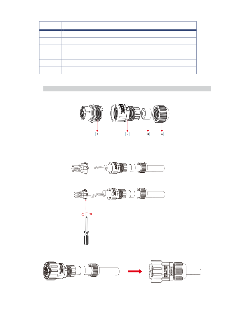
    Unscrew the nut, sealing, body, and housing of the CT connector.
    1
    Housing
    2
    Body
    3
    Sealing
    4
    Nut
    Step 2. Thread the wires of the CTs through the nut, sealing, and the body, insert
    them into the pins of the CT connector, and then tighten the screws.
    Step 3. Tighten the nut, sealing, body, and housing of the CT connector.
    Step 4. Plug the CT connector into the CT port inside the inverter and tighten it.
    55

    Page 56

    Original PDF
    T CT-(Black)
    R CT+(White)
    R CT-(Black)
    T CT+(White)
    S CT-(Black)
    S CT+(White)
    White cable
    Black cable
    “*” indicates the same terminal
    NOTE
    CT port: Point the arrows toward the grid.
    4.4.8 Connecting a Smart Meter
    You must connect external CT or a smart grid meter between the inverter and the power grid.
    If you want to connect external CT, see Connecting External CT.
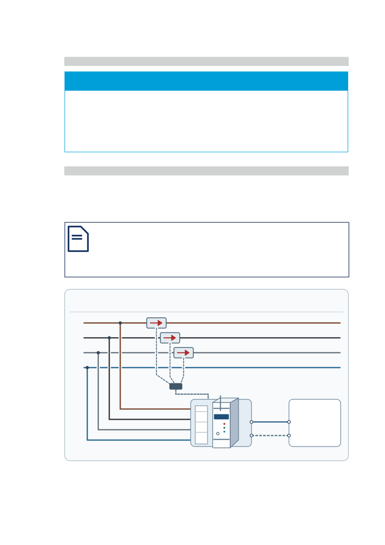
    If you want to connect a smart meter, note that only one meter is necessary for each inverter. The meter must be mounted and connected at the grid transition point (feed-in point) so that it can measure the grid reference and feed-in power.
    To connect a smart meter, a meter connector is necessary and it must be connected to the DRY/METER port inside the inverter.
    Pin Description of METER+DRY Port
    PIN
    Description
    1
    DRY contact
    2
    DRY contact
    3
    GND
    4
    Input signal
    5
    RS485-B
    6
    RS485-A
    56

    Page 57

    Original PDF
    NOTES
    NOTICE
    Use Eastron SEM3-WL-2 for the connection shown. Check that your Infinity firmware supports the meter.
    Use the supplied CT set. During commissioning, verify that a known draw from the grid is shown as import.
    PROCEDURE
    Step 1.
    Prepare the communication wires, power cable, and tools for the meter connection.
    Step 2.
    Connect L1, L2, L3 and N as shown in Eastron’s 3P4W diagram. Match CT1 to L1, CT2 to L2 and CT3 to L3.
    NOTE
    The arrows on the SEM3-WL-2 CTs must point from the grid toward the house.
    Figure 4-25 Wiring of Smart Meter Connection · Eastron SEM3-WL-2
    Step 3.
    RS485 · A+ → 6 (RS485-A) · B− → 5 (RS485-B)
    57
    GRID
    3P4W
    House / loads
    L1
    L2
    L3
    N
    CT1
    CT2
    CT3
    CT / RJ12
    Eastron SEM3-WL-2
    L1
    L2
    L3
    N
    RS485
    A+
    B−
    Infinity
    DRY/METER
    6 · RS485-A
    5 · RS485-B

    Page 58

    Original PDF
    4.4.9
    (Optional) Connecting a DRED or an RRCR
    NOTES
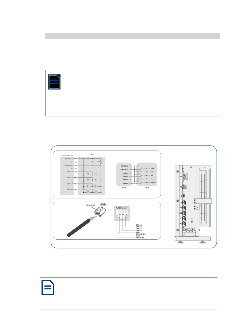
    The INF-4-0/INF-5-0/INF-6-0/INF-8-0/INF-10-0/INF-10-0-BE/INF-12-0 complies with AS/NZS 4777.2:2015 standard. Its DRM port can be connected to a Demand Response Enabling Device (DRED) in Australia or New Zealand or a Radio Ripple Control Receiver (RRCR) in other areas or countries.
    NOTE
    When the Australia or the New Zealand grid standard is selected, the DRM port can be enabled to connect a DRED. When other grid standards are selected, this port can be enabled to connect an RRCR. For more information about grid standards, see GRID CODE.
    A DRM connector is necessary for the connection. Table 4-4 shows the pin descriptions of the DRM connector.
    Table 4-DRM Connector Pin Descriptions
    The INF-4-0/INF-5-0/INF-6-0/INF-8-0/INF-10-0/INF-10-0-BE/INF-12-0 is pre- configured to the following Radio Ripple Control Receiver (RRCR) power levels as shown in Table 4-5.
    NOTE
    In the “PIN x” columns, “0” means the corresponding relay is closed and “1” means the corresponding relay is opened.
    58
    Rj45 plug

    Page 59

    Original PDF
    Table 4-5 RRCR Power Level
    PIN8
    PIN7
    PIN6
    PIN5
    PIN3
    Active Power
    Cos(Q)
    1
    0
    1
    1
    1
    0%
    1
    1
    1
    0
    1
    1
    30%
    1
    1
    1
    1
    0
    1
    60%
    1
    1
    1
    1
    1
    0
    100%
    1
    1
    1
    1
    1
    1
    100%
    1
    0
    X
    X
    X
    X
    Standby
    1
    PROCEDURE
    Step 1.
    Make sure that DRM is enabled in the integrated EMS. For more information, see the DRM ENABLE subsection under Advanced Function.
    Step 2.
    Use the DRM connector to connect the DRM port inside the cable box to the external device.
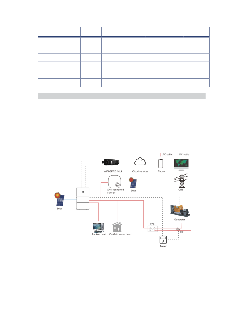
    4.4.10 (Optional) Connecting a Generator
    If you are using a generator, you can connect the generator to the INF-4-0/INF-5- 0/INF-6-0/INF-8-0/INF-10-0/INF-10-0-BE/INF-12-0 energy storage system.
    Figure 4-26 Connect a Generator
    59
    AC cableDC cableCloud servicesPhoneWiFi/GPRS StickGrid-connectedInverterSolarSolarBackup Load On-Grid Home LoadMeter

    Page 60

    Original PDF
    4.5
    Installing a Parallel System
    The INF-4-0/INF-5-0/INF-6-0/INF-8-0/INF-10-0/INF-10-0-BE/INF-12-0 supports installation of a parallel system with more than one inverter. A maximum of four inverters can be connected in parallel. For more information, see Parallel System.
    4.5.1
    Wiring of a Parallel System
    Follow these figures for wiring of a parallel system with two, three, or four inverters.
    NOTE
    The lengths of the three branch cables from the AC output circuit breaker to the power module must be kept consistent.
    60

    Page 61

    Original PDF
    Figure 4-28 Wiring of a Parallel System with Four Inverters
    • Connecting the Inverter and PV Solar Panels.
    • Make sure that all the battery packs are mounted and connected. For more
    information, see Mounting the All in One system and Connecting Battery Packs (BP48100PF1A-G2).
    • Make sure that the grid and load connections to each inverter are correct. For more
    information, see Connecting to Grid and Loads.
    • Decide which inverter serve as the primary inverter.
    61

    Page 62

    Original PDF
    NOTE
    Make sure that only the primary inverter connects a set of CT or an electricity meter. DO NOT connect CT or an electricity meter to the subordinate inverters. For more information, see Connecting External CT or Connecting a Smart Meter.
    • Make sure that the AC circuit breakers in the distribution box are in the OFF state.
    • Prepare the parallel connectors and network cable.
    The recommended maximum length of the communications cable between parallel inverters is 10 m.
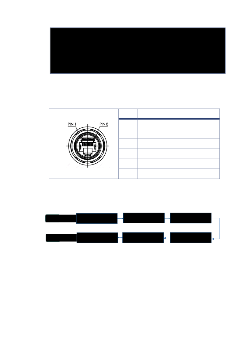
    Table 4-7 Pin Description of the Parallel Ports
    Pin
    Description
    1
    CAN_H
    2
    CAN_L
    3
    INV_STATUS_BC
    4
    BPSIDE_HOLD_BC
    5
    MASTER_SYN_BC
    6, 7, 8
    GND
    5
    Commissioning
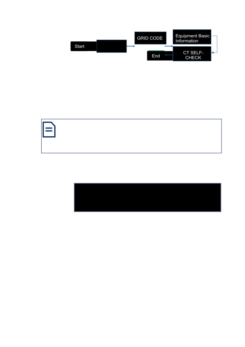
    Follow the steps in Figure 5-1 to commission the system.
    Set common parameters
    Check before power-on
    Power on
    Start
    Check the settings
    CT SELF CHK
    End
    Power off
    Figure 5-1 Commissioning Procedure
    5.1
    Checking Before Power-on
    Before powering on the system, thoroughly check the installation.
    Step 1.
    Make sure that the INF-4-0/INF-5-0/INF-6-0/INF-8-0/INF-10- 0/INF-10-0-BE/INF-12-0 is firmly fastened to the mounting panel on the wall.
    Step 2.
    Check the electrical connection inside the inverter. Make sure that:
    • PV+ and PV- cables are firmly connected and the polarity and voltage
    are correct.
    • The ON GRID and BACK UP cables are connected firmly and correctly.
    62

    Page 63

    Original PDF
    Step 3.
    Check the electrical connection in the inverter. Make sure that:
    • The AC circuit breakers for the normal loads are correctly connected.
    • The AC circuit breakers for the BACK UP loads are correctly connected.
    • Both breakers are in the OFF state.
    5.2
    Powering On
    NOTICE
    If PV output voltage is 0 V in sunlight, check the PV connection. Check for reverse connection of the PV and make sure that the circuit connection is correct.
    Step 1.
    Turn on the external PV switch.
    Step 2.
    Remove the decorative panels on both sides of the inverter.
    Step 3.
    First, turn on the circuit breaker switch on the battery pack, and then long press the battery button next to the inverter (1-3 seconds) until the green light on the battery button lights up.
    Step 4.
    Beside the inverter, turn on the PV Switch.
    Step 5.
    In the distribution box, turn on the AC current breaker between the ON GRID port and the grid.
    Step 6.
    In the distribution box, turn on the AC breaker between the BACK UP port and the BACK UP loads.
    NOTE
    The LOAD Switch is necessary only when a EPS load is connected.
    Step 7. Reinstall the decorative panels on both sides of the inverter.
    5.3
    Setting Common Parameters for the System
    NOTE
    In a parallel system, all settings must be the same for all inverters except for the addresses of the inverters.
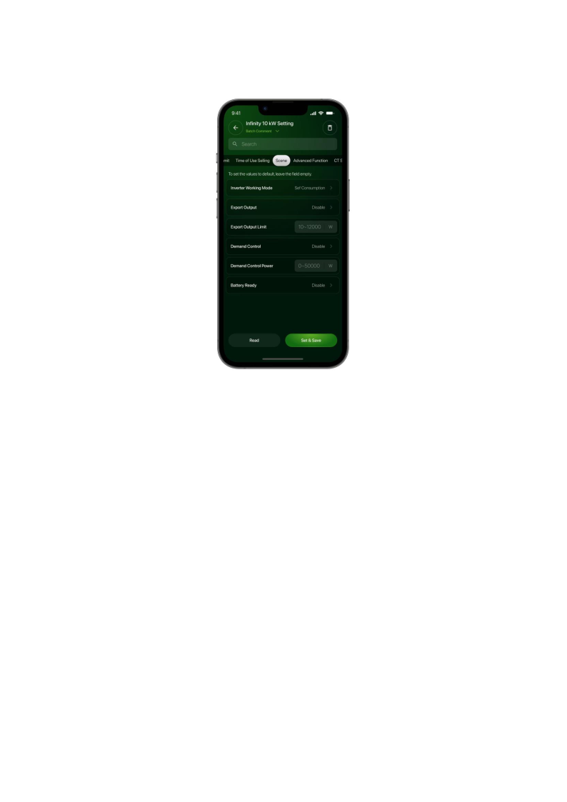
    When the energy storage system is powered on, On the mobile phone, enter the settings page through Green Hero to configure the general parameters.
    Step 1.
    Set the working mode of the system. For more information, see the WORK MODE subsection under Scene setting.
    Step 2.
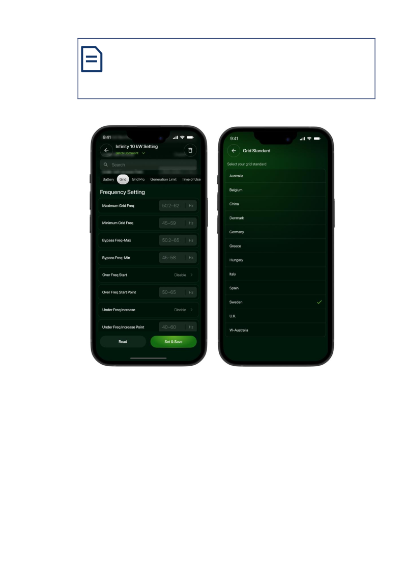
    Select the grid standard. For more information, see GRID CODE.
    Step 3.
    Set date and time of the system. For more information, see Equipment
    63

    Page 64

    Original PDF
    Temperature: Depends on the ambient temperature around the system.
    Voltage: Must be within the 50 V ± 3 V range.
    Capacity: The capacity of a battery is 100 Ah. When more than one battery pack is connected in parallel, the capacity of the system is 100 Ah multiplied by the number of battery packs.
    Basic Information.
    Scene setting
    Figure 5-2 Set Common Parameters
    If you want to set more parameters for the system, see Setting up the System.
    5.4
    Checking the Settings
    When the energy storage system is powered on, check the settings of the battery pack, PV, and grid to make sure that the system can work correctly.
    NOTE
    To calibrate the SOC of the battery, after the system is installed, the batteries must be charged to 100% SOC once.
    Step 1.
    Follow these steps to check the battery information:
    1.1
    Open the decorative covers on both sides of the inverter
    NOTE
    Make sure no red indicator light is ON.
    1.2
    Press the power button (1–3 s) until the light on the button comes on.
    View battery settings and BMS parameters in the Green Hero app.
    1.3
    •
    •
    •
    Step 2.
    After PV input is connected and the PV Switch beside the inverter is turned on, check the information on the PV1 INPUT and the PV2 INPUT page. For more information, see Viewing the Current System Information.
    Step 3.
    After ON GRID connection is done, check the information on the GRID VOLT page. For more information, see Viewing the Current System Information.
    64

    Page 65

    Original PDF
    5.5
    Powering off
    WARNING
    To prevent damage or personal injury, after the equipment is turned off, DO NOT begin maintenance work until 5 minutes have passed.
    Step 1. If BACK UP loads are applied, turn off the LOAD Switch In the distribution
    box and the AC current breaker between the LOAD port and critical load.
    Step 2. In the distribution box, turn off the AC current breaker between ON
    GRID port and the grid.
    Step 3. Press the battery buttons (1~3 seconds) until the indicator light of the
    power button goes out. Finally, turn off the circuit breaker switch on the battery pack.
    Step 4. Beside the inverter, turn off the PV Switch.
    Precaution:
    Please make sure that the battery is not being charged or discharged before performing a shutdown.
    6
    System Operation
    6.1
    Download APP and registration
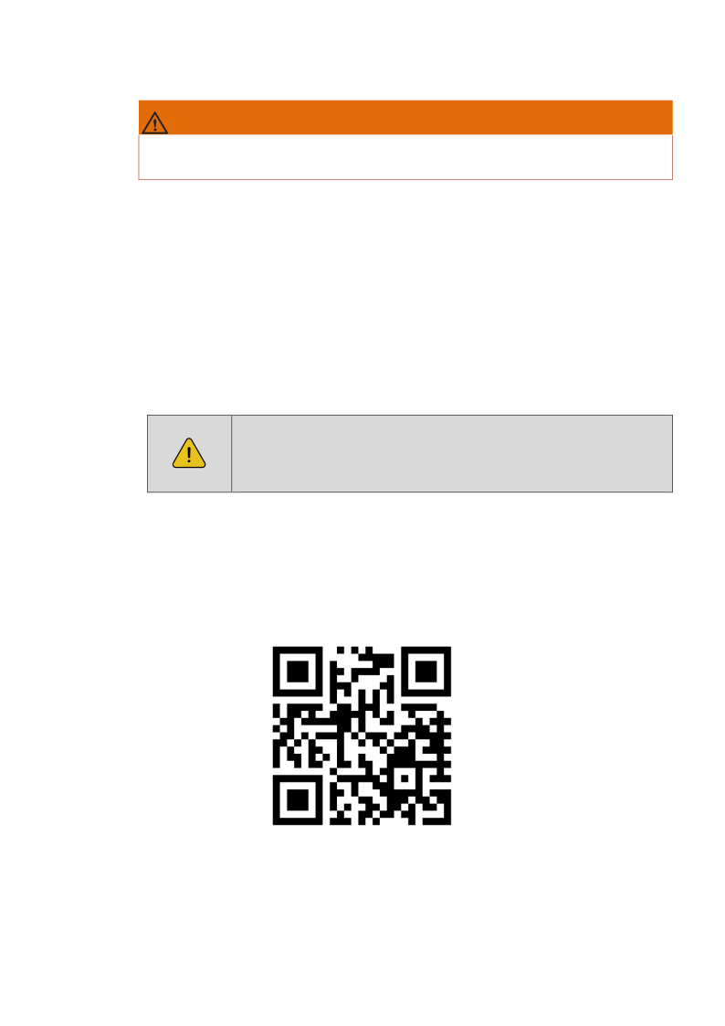
    If you are a household user, please scan QR code below to download Green Hero APP.
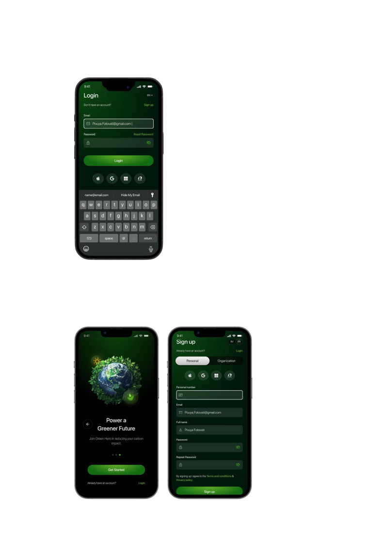
    After entering Green Hero App, please register at Green Hero App to ensure the normal function. Click "Sign up" to continue. Always register with E-mail firstly, you can then bind other login methods such as Apple and Google account and Bank ID. Please follow:
    65

    Page 66

    Original PDF
    Login
    If you have an account at Green Hero, you can login directly.
    Setup Account
    1) Swipe thru get started frames
    2) Fill in all fields and press Sign up.
    3) Verify your account with the verification email
    4) Your account has been setup
    66

    Page 67

    Original PDF
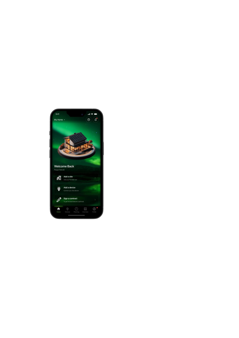
    Sign a contract
    It is recommended to sign a contract to get the most out of your products & services.
    1) Choose in the Home Tab choose Sign a Contract. If you already have a contract,
    choose, I already have a contract
    2) Fill the necessary field.
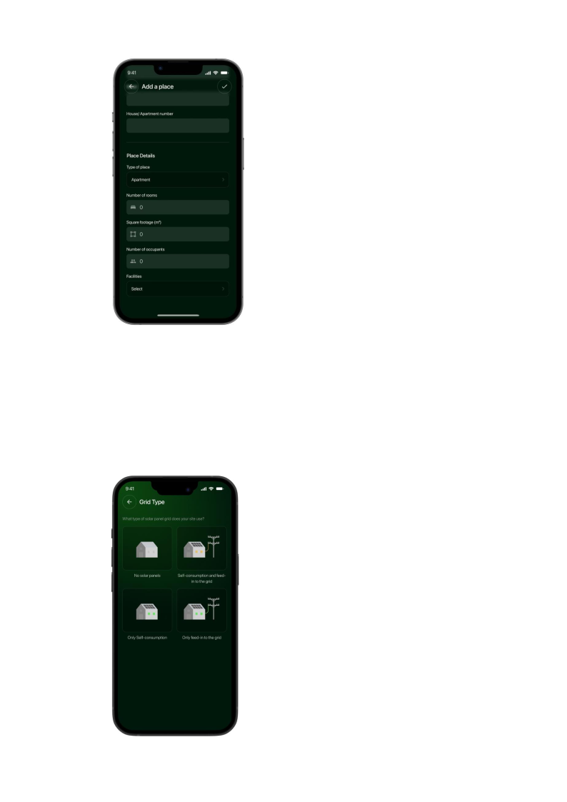
    Create a Site If you don’t have a contract you need to create a Place. You can create your own Place at "Green Hero APP" to run a real-time monitoring. System will collect and calculate data from associated devices, which enables a full understanding of PV plant running status.
    Step 1: Add a Site Click " Add a site " to create your Place in Green Hero APP Home tab.
    Notice: If you have already created a Site, you will not see the following page in the Home Tab anymore. If you wish to create another Site, please click "My Sites" in the upper-left corner and click the "+" in the popup window.
    67

    Page 68

    Original PDF
    Step 2: Enter Home Details Please enter detailed home information according to your actual situation. System will create a unique home for you. In order to calculate plant data precisely, please enter      
    Site Name,
    Site Type,
    Site Size
    Grid Type,
    Home Location,
    Other information.
    68

    Page 69

    Original PDF
    Connect your device to the APP After the Site is created, you can add a device. The dongle can collect running data from PV devices and upload to server, which enables a full understanding of PV plant running status and revenue information. Furthermore, Green Hero will determine whether the plant is running normally, which avoid property losses caused by device failure and other reasons.
    Step 1: Select a Site In case you have various power Sites, which might cause data corruption, it is recommended to select a Site first before adding a device. Ways to add a device : 1)Go to "Devices" , click "Inverters" in the middle, select "Add an inverter", then Select a Site according to your actual situation. Scan QR code of the dongle of the inverter to connect the inverter to the to the target site.
    2)The dongle will autodetect devices it is connected to and devices on the network
    with an open Modbus port and display a list of found devices choose the device you want to connect. When choosing an inverter, it will automatically scan for batteries make sure all batteries appear in the list and press continue.
    69

    Page 70

    Original PDF
    Network Settings If the dongle is connected to ethernet and shows the status online no further steps is needed. To ensure the capability of running all services and the best user experience make sure to use ethernet, some service may not be available without ethernet connection. It is required to operate networking configuration to ensure normal communication.
    The dongle is equipped with WiFi, to setup WiFi please follow these steps Go to Devices  Inverters  Choose the Infinity you want to setup Wi-Fi on. In the top right corner there is a Wi-Fi Icon press it, then press Online Access Configuration (Wi-Fi Configuration).
    70

    Page 71

    Original PDF
    1. Networking Process
    Step 1: Press connect to inverter, your phone will prompt you thru a systems message asking if you want to connect to the network that the APP displays, do that to get local access. "Connect to inverter"
    Step 2: Connect to your Wi-Fi network, choose your network in the list and type the password then press “Connect".
    71

    Page 72

    Original PDF
    Step 3: Auto Configuration Please wait for a while to complete the configuration. Once finished and successful press Done. When you go back to 「Device List」, the Dongle can still be at Offline status. Usually, the data will be updated within 10 mins. Please wait patiently.
    If configuration failure occurs, please check the following reasons and try it again.
    1. Make sure WLAN is ON;
    2. Make sure WiFi is normal;
    3. Make sure wireless router does not implement the white-black list;
    4. Shorten the distance between the phone and device;
    5. Try to connect to other Wi-Fi;
    6. Remove the special characters(,;‘’=“”`) in Wi-Fi network.
    6.2
    Local Access Press the Wi-Fi Icon in Inverter Details Dasboard, choose Local Access. In the local access connection view press “Connect to Inverter”. Once the communication between the inverter and the app is established, you can access the inverter settings interface.
    72

    Page 73

    Original PDF
    6.2.1
    Battery setting
    In this setting, battery parameters can be configured.
    1. ON grid/Off grid discharge depth: Set the maximum depth of discharge (DoD)
    for both grid-connected and off-grid modes. The default is 90%, with an adjustable range of 5% to 90%. Additionally, ensure that the depth of discharge enable setting is activated.
    2. Bat discharge/charge power setting: Set the battery discharge and charge
    power percentage. The adjustable range is 0–100%, with a default value of 100%.
    3. Bat set charge current: Set the battery charging current, adjustable range:
    4 kW: 1–100 A, 5/6 kW: 1–120 A, 8 kW: 1–160 A, 10/12 kW: 1–200 A
    4. Wake-up BMS Time: When the battery is in hibernation, the inverter wakes the
    battery at regular intervals, with a configurable range of 5-300 minutes. At the same time, the depth of discharge enable setting needs to be activated.
    5. Force charge/discharge Enable: There are three modes: Invalid, Charge, and
    Discharge.
    6. Charge from grid Max SOC: After setting the Charge source, the SOC for
    charging the battery from the Charge source can be configured.
    7. Enabling Discharge Depth can prevent the battery from discharging to 0%.
    73

    Page 74

    Original PDF
    Battery Self Check
    This function is used to calibrate the SOC of the Li-Ion battery. By default, when the SOC of the Li-Ion battery does not reach 100% for 30 consecutive days, the inverter will force charge the Li-Ion battery until the SOC of the Li-Ion battery reaches 100%.
    Time setting range: 7~100 (day)
    MAINTAIN SOC
    When MAINTAIN SOC is enabled, the minimum battery SOC is maintained. The minimum battery SOC is 2%. When the battery SOC is less than 2%, the grid charges the battery to 5% through the inverter.
    BAT WAKE-UP
    The battery will go to sleep in these states:
    Over-discharge protection.
    No communication between the battery and the external and no charging or discharging current for a period.
    By default, the system monitors the SOC and DOD of the batteries. You can set the system to wake up the batteries from sleep and to check the SOC and DOD at a set interval.
    74

    Page 75

    Original PDF
    The range for this parameter is 0–300 minutes.
    HEATING FILM
    NOTE
    Only applicable to the batteries with heating films.
    By default, the setting is AUTOMATIC. It means the film is automatically turned on or off based on the ambient temperature.
    6.2.2
    Battery pack parameters
    Under this project, you can view the SOC, SOH, cycle count, and cumulative discharge of all connected battery packs.
    6.2.3
    GRID CODE
    Under this setting, you can choose the grid standard that applies to your energy storage system, with the default set to the local standard.
    75

    Page 76

    Original PDF
    NOTE
    Local is a customized grid standard that specifies the widest output voltage range and output frequency range. It is applicable to most energy storage systems.
    Table 6-1 lists the specifications of different grid standards.
    76

    Page 77

    Original PDF
    Table 6-1 Grid Specifications
    Output
    Output Voltage
    Start
    Frequency (Hz)
    Grid
    Range (VAC)
    Delay (s)
    1
    China
    187–252
    49.5–50.2
    30
    2
    Germany
    184–264
    47.5–51.5
    60
    AUS-A
    180–265
    47–52
    60
    AUS-B
    180–265
    47–52
    60
    3 Australia
    AUS-C
    180–265
    45–55
    60
    CEI0-21
    195–264
    49.8–50.2
    60
    4 Italy
    CEI0-21 ACEA
    195–264
    49.8–50.2
    60
    5
    Spain
    196–253
    48–50.5
    180
    6
    U.K.
    184–264
    47–52
    180
    7
    Hungary
    196–253
    49–51
    300
    8
    Belgium
    184–264
    47.5–51.5
    60
    9
    New Zealand
    180–260
    45–52
    60
    10
    Greece
    184–264
    49.5–50.5
    180
    11
    France
    184–264
    47.5–50.4
    60
    12
    Bangkok
    198–242
    49–51
    150
    13
    Thailand
    198–242
    47–52
    60
    14
    South Africa
    180–260
    47.0–52
    60
    15
    50549
    184–264
    47.5–51.5
    60
    16
    Brazil
    184–264
    59.5–60.5
    60
    17
    0126
    184–264
    47.5–51.5
    60
    18
    Ireland
    184–264
    47–52
    180
    19
    Israel
    195.5–253
    47.0–51.5
    60
    20
    Poland
    195.5–253
    49.00–50.05
    60
    Chile-BT
    176.0–242
    47.5–51.5
    60
    Chile-HD
    198.0–242
    49–51
    300
    21 Chile
    Chile-LD
    198.0–242
    49–51
    300
    22
    Local
    150–280
    45.0–55
    30
    23
    60 Hz
    184–264
    59.5–60.5
    60
    24
    Denmark
    195.5–253.0
    47.5–51.5
    60
    25
    Sweden
    195.5–253.0
    47.5–51.5
    60
    26
    Austria
    184–264.5
    47.5–51.5
    300
    27
    Czech
    195.5-253
    47.5-52
    60
    28
    Cyprus
    184-253
    47-51.5
    180
    77

    Page 78

    Original PDF
    29
    Netherlands
    184-253
    48-51
    60
    30
    Switzerland
    184-276
    47.5-51.5
    60
    6.2.4
    Grid setting
    When you select the grid standard in GRID CODE, these parameters are set automatically. During operation, when the inverter detects that these settings have been reached or exceeded, the inverter stops generating power.
    NOTE
    Changing the setting of these parameters is not recommended. After adjusting one or more parameters, please restart the system. Reboot the inverter to view System-setting
    Settings
    • POWER FACTOR: The acceptable range is L0.8–L1.00 and C0.8–C1.00.
    The default setting is PF1.0.
    • REACT POWER: The acceptable range is L00%–L60% and C00%–C60%.
    • Reactive power control: By default, both are disabled.
    GRID POWER
    Active setting: The setting value is a percentage of the rated power of the system. It can be set from 0% to 100%, and the default value is 100%.
    GRID U and GRID F:
    Table 6-3 BYPASS Parameters for Run Setting
    Parameter
    Description
    Default
    GRID U MAX
    270 VAC
    Maximum voltage of the grid
    GRID U MIN
    180 VAC
    Minimum voltage of the grid
    GRID F MAX
    52.5 Hz
    Maximum frequency of the grid
    GRID F MIN
    47 Hz
    Minimum frequency of the grid
    BYPASS U MAX
    Maximum voltage of the grid
    270 VAC
    BYPASS U MIN
    Minimum voltage of the grid
    180 VAC
    BYPASS F MAX
    Maximum frequency of the grid
    52.5 Hz
    BYPASS F MIN
    Minimum frequency of the grid
    47 Hz
    OVER VOLT and UNDER VOLT:
    By default, OVER VOLT and UNDER VOLT are disabled. You can enable them and set the voltages. OVER VOLT: When it is enabled, you can set VOLT. If the AC output voltage is higher than the set value, the output power decreases. The default value of VOLT
    78

    Page 79

    Original PDF
    is 270 V.
    UNDER VOLT: When it is enabled, you can set VOLT. If the AC output voltage is lower than the set value, the output power decreases. The default value of VOLT is 200 V.
    OVER FREQ and UNDER FREQ By default, OVER FREQ and UNDER FREQ are disabled. You can enable them and set the frequencies: OVER FREQ: When it is enabled, you can set FREQ. If the AC output frequency is higher than the set value, the output power decreases. The default value of FREQ is 52 Hz. UNDER FREQ: When it is enabled, you can set FREQ. If the AC output frequency is lower than the set value, the output power decreases. The default value of FREQ is 48 Hz.
    NOTE
    By default, the above four types of derating are disabled. If you need to use this function, you need to enable it manually.
    QU-Response Time
    QU-Response Time allows you to set the necessary time for the output reactive power to reach the grid standard level. The selected grid standard determines the time, so DO NOT change it if the grid is not changed. The default value is 15 seconds
    Soft Start Ramp Rate
    Soft Start Ramp Rate means the change of output power per minute.
    The selected grid standard determines the rate, so DO NOT change it if the grid is not changed. The value of 100% means that the output power can reach the rated power within one minute. The range for this parameter is 0% to 300%, and the default value is 100%.
    GFCI CHK ENB
    The INF-4-0/INF-5-0/INF-6-0/INF-8-0/INF-10-0/INF-10-0-BE/INF-12-0 supports a connection of ground failure circuit interrupter to monitor the AC grid connection. By default, this feature is enabled.
    VRT ENABLE
    VRT ENABLE is to enable or disable voltage-ride-through.
    When you select the grid standard in Grid Setting, VRT ENABLE is set automatically.
    79

    Page 80

    Original PDF
    NOTE
    Changing the setting of VRT ENABLE is not recommended.
    6.2.5
    Scene setting
    WORK MODE
    The INF-4-0/INF-5-0/INF-6-0/INF-8-0/INF-10-0/INF-10-0-BE/INF-12-0 supports three working modes: SELF CONSUME, PEAK SHIFT, and BAT PRIORITY. For more information, see Working Modes.
    SELF CONSUME: This is the default working mode. In this mode, the batteries are charged by the PV panel by default.
    On the CHARGE FROM GRID page, you can enable the batteries to be charged by the grid. When SELF consumption charge Enable is enabled, you can set the time(up to two each) and the maximum SOC for charging. Charging will automatically stop when the set time or MAX SOC is reached.
    PEAK SHIFT: During the charging time, the batteries are forced to be charged by the grid and/or the PV panels. During the discharging time, the batteries are forced to be discharged to the connected load. You can set times for charging and discharging (up to five each), select CHARGE or DISCHR through the Green Hero App to charge or discharge the battery. During the charging time, the batteries are forced to be charged by the grid and/or the PV panels. During the discharging time, the batteries are forced to be discharged to the connected load.
    80

    Page 81

    Original PDF
    BAT PRIORITY: This mode is also known as the UPS mode, which is used in situations where a battery serves as a BACK UP power source. The battery only discharges when the grid power is down, helping to extend the battery's lifespan. If the battery is not fully charged, it will continue charging, and the charging power can come from either solar power or the utility grid. The goal is to keep the battery fully charged. During a power outage, the system operates off-grid to provide power to the BACK UP, which can be understood as the BACK UP function of a UPS.
    ZERO EXPORT
    By default, this feature is disabled. When the feature is enabled, the system outputs power to the grid and you can set the power limit in the range from 10 W to the rated power of the system.
    Peak Shaving Power Enable
    After enabling the peak shift power control, you can set the peak power and valley power of the load power.
    NOTE
    The peak power setting value must be greater than the valley power, otherwise the setting will be invalid.
    The operation logic is shown in the figure:
    Demand control Enable
    1. This function is applicable to any operating mode of the inverter when drawing
    power from the grid.
    2. This function is designed to limit the amount of power drawn by the inverter
    from the grid. By enabling the "demand control" setting and setting the
    81

    Page 82

    Original PDF
    demand power in the range of 0–20,000 W. When this function is active, load power + charging power = demand power.
    6.2.6
    Advanced Function
    REMOTE CTRL
    Remote control to turn the inverter on and off. By default, this feature is enabled.
    START DELAY
    By default, when power is supplied to the inverter, there is a 30-second delay before the inverter starts.
    You can increase or decrease the delay time in the range of 20–300 seconds. See GRID CODE for the start delay time for the selected grid standard.
    CEI SPI CTRL
    The E8KT/E10KT/E12KT supports the CEI 0:21 standard. Currently, this feature is applicable in Italy only.
    When Italy is selected as the grid standard, you can select OPERAT MODE through the setting of CEI SPI CTRL and the states of PIN1 and PIN7 of the DRM port:
    When PIN1 and PIN7 are not shorted and CEI SPI CTRL is disabled, Transient is enabled for OPERAT MODE.
    82

    Page 83

    Original PDF
    When PIN1 and PIN7 are shorted and CEI SPI CTRL is enabled, Final is enabled for OPERAT MODE.
    By default, this feature is disabled.
    AUTO TEST
    In Italy, when an E8KT/E10KT/E12KT energy storage system is installed, it must
    pass the AUTO TEST in the specified operate mode before being connected to the
    local grid. For more information about the operate mode, see OPERAT MODE.
    NOTE
    AUTO TEST is only applicable in Italy.
    When an operate mode is specified, follow these steps to run the AUTO TEST:
    Step 1. Select AUTO TEST.
    Step 2. Enter your password. The default password is 00000. If you have changed the password, use the new password.
    If the password is correct, a countdown page is shown on the screen. When the countdown ends, the automatic test starts. When the automatic test ends, Pass or Fail is shown. If the result is Fail, run the automatic test again. If you run the test multiple times and the result is always Fail, contact Company.
    CT SELF CHK
    When three external CTs are connected to the inverter, you can run a CT self- check. A CT self-check lasts 1–5 minutes.
    Before running a CT self-check, make sure that all these operations are done:
    Step 1. Connect external CTs. For more information, see Connecting External CTs.
    Step 2. Connect the inverter to the battery packs and the power grid.
    These errors can occur during a CT self-check:
    83

    Page 84

    Original PDF
    • Battery loss, fail to check: Means no battery packs are connected to the
    system, so the CT self-check cannot be completed. You must connect battery packs and try the CT self-check again.
    • Grid loss, fail to check: Means the system is not connected to the grid, so
    the CT self-check cannot be completed. You must connect the system to the grid and try the CT self-check again.
    • CT loss, fail to check: Means no external CTs are connected to the system,
    so the CT self-check cannot be completed. You must connect external CTs to the system and try the CT self-check again.
    • Timeout, fail to check: Means the CT self-check timeout. Make sure that
    limits have not been placed on the charging and discharging power, because the power on each phase of the grid must be greater than 1 kW during a CT self-check. To achieve this, DISC POWER, CHG POWER, and GRID POWER must be set to 100% and CHG CURR must be set to 160 A. For more information, see the DISC POWER, CHG POWER, and CHG CURR subsections under BAT SETTING, and the GRID POWER subsection under RUN SETTING.
    VPP Function
    Enable VPP power control. When it is enabled, inverter power follows only the power target received over RS485, regardless of the selected base mode. Set the power target as follows.
    Step 1. Enable VPP control via RS485:
    Address: 3270 1: Enable 0: Prohibit
    Write "1" to address 3270, set VPP enable,
    Write "0" to address 3270, disable VPP, and run the inverter in the operating mode set by LCD: self-consumption, peak shaving and battery priority.
    Default to '0' prohibit
    Step 2. Set RS485 power:
    Address: 3267, default value is "0", setting range: 0~± Rated Powerge
    Writing 3000 W to address 3267 sets inverter power to 3000 W exported to the grid.
    Writing -3000 W to address 3267 sets battery charging power to 3000 W.
    Step 3. Disable VPP
    Address: 3270 1: Enable 0: Prohibit
    84

    Page 85

    Original PDF
    Write 0 to address 3270 to disable VPP. The inverter then operates in the mode selected on the LCD: self-consumption, peak shaving or battery priority.
    NOTE
    1. When "3270" is disabled and a power not equal to 0 is written to 3267, the 3270 address will automatically become 1 and the VPP function will be enabled;
    2. When 3270 is enabled, write "0" power to 3267, and the inverter controls the inverter power to "0";
    3. VPP is prohibited. VPP will only be disabled when writing 0 to 3270, and VPP function will not be disabled when writing 0 to "3267".
    GENERATOR
    You can use a generator, for example, a wind generator or a diesel generator, as a backup supply to the E8KT/E10KT/E12KT energy storage system.
    By default, this feature is disabled. When the generator is manually switched into the system, select "Manual".
    When the generator is automatically switched into the system through devices like an ATS (Automatic Transfer Switch), select "Auto".
    When "Auto" is selected, it is necessary to set the battery SOC (State of Charge) for starting and stopping the generator, as well as choose between normally open and normally closed contacts.
    When the battery SOC is below the set value and the power grid is out of power, the generator will start;
    When the battery SOC is above the set value or the power grid is restored, the generator will stop;
    0 represents a closed dry contact, and 1 represents an open dry contact.
    Configurable range of DG On SOC:10%~90%;
    Configurable range of DG Off SOC:15%~100%.
    ISLAND
    •
    To enable anti-islanding protection. This is for use by maintenance personnel only.
    CT OR METER
    The INF-4-0/INF-5-0/INF-6-0/INF-8-0/INF-10-0/INF-10-0-BE/INF-12-0 support connecting external CT or a smart meter for measuring the energy consumption.
    By default, CT is selected.
    85

    Page 86

    Original PDF
    PV INPUT
    There are two modes for PV inputs: independent and parallel. Set the appropriate PV input mode based on the actual connection of the PV strings.
    INDEPENDENT is selected by default. Selecting it when the PV strings are connected in parallel causes an uneven distribution of power between the strings.
    PV INPUT
    The INF-4-0/INF-5-0/INF-6-0/INF-8-0/INF-10-0/INF-10-0-BE/INF-12-0 supports DRM.
    By default, this feature is disabled. In the countries where DRM is mandatory, enable the DRM feature. When the DRM connection is done, you must set DRM ENABLE to ENABLE. For more information about DRED connection, see (Optional) Connecting a DRED or an RRCR.
    PV INPUT
    If you want to connect an inverter to your PV panels to build an AC-coupling system, you must enable AC COUPLE.
    By default, this feature is disabled. For more information, see AC-coupling System.
    PARALLEL
    When more than one inverter is installed in parallel, you must enable PARALLEL and set the addresses for the inverters.
    When a parallel system is installed and PARALLEL is enabled, assign an address (a value from 1 to 4) to each inverter. The address of the primary inverter must be set to 1. A maximum of four inverters are supported. For more information, see Installing a Parallel System.
    If it is used in parallel only on the grid side, select "On Grid".
    If it is used in parallel on both the grid side and the backup side, select "On & Off
    By default, this feature is disabled.
    AFCI
    The inverter has an AFCI protection feature.
    By default, this feature is disabled. When it is enabled, dangerous arcing faults on the PV panels can be detected. You can set the detection level for AFCI protection to a value from 1 to 9. The lower the value, the lower the AFCI threshold.
    86

    Page 87

    Original PDF
    CYBERSAFETY
    Currently, this feature is applicable in UK only.
    The inverter supports remote control of the inverter.
    On the CYBERSAFETY page, you have two options:
    Modbus Write: To enable or disable remote control of the inverter. When this feature is enabled, you can control the inverter on the data-monitoring page.
    Upgrade: When this feature is enabled, you can upgrade the firmware of the inverter or the battery packs remotely.
    GRID TYPE
    The inverter provides two grid-connected power output modes:
    Mixed Mode: When the inverter is connected to the grid, the three phases output the same power.
    Independent: When the inverter is connected to the grid, the three phases can output different power.
    You can select the appropriate grid-connected power output mode in the integrated EMS:
    HEAT PUMP
    1. When the power fed to the grid exceeds 3000W (this value is adjustable and can be set based on the heat pump’s power in the APP), the heat pump will start.
    2. When the SOC is greater than the set value within the preset time period, the heat pump will start
    SOC setting range: 0-99%. Default: 60%.
    BAT READY Enable this function to suppress battery-related alarm messages when used without battery connection.
    Demand Ctrl
    Set the maximum power drawn from the grid.
    87

    Page 88

    Original PDF
    PV Start Voltage
    This setting allows you to configure the inverter's PV startup voltage. When the PV voltage is lower than the startup value, the inverter will not operate.
    NOTE
    The settings GRID setting2, QU-Set, P(U)&P(f), Reconnect& VRT, and QP-SET are all set to default. It is not recommended for non-staff to modify these settings.
    6.2.7
    System-setting
    Reboot Inverter The command can be issued to restart the inverter.
    Factory Data Reset You can reset the inverter to the default factory settings.
    Clear statistics The command issued will clear all statistical information.
    Remote Shutdown After enabling REMOTE CTRL, sending this command will put the inverter into standby mode. After disabling this function, the inverter will return to normal operation.
    88

    Page 89

    Original PDF
    6.2.8
    Equipment Basic Information
    • FIRMWARE: The version of the firmware in ARM and DSP.
    • MODEL SN: The serial number of the hybrid inverter in use.
    • INV MODEL: The model of the hybrid inverter in use.
    • Bat Name: The serial number of the battery in use.
    • System Time : setting the date, time, and day of the week for the system.
    6.2.9
    PV information
    In this interface, you can view the voltage, current, and power of the two
    89

    Page 90

    Original PDF
    photovoltaic inputs, PV1 and PV2, of the inverter.
    6.2.10
    Alert
    The fault codes of the inverter in operation can be viewed on this interface.
    6.2.11
    Temperature
    In this interface, you can view the real-time temperature status of the five internal points of the inverter.
    90

    Page 91

    Original PDF
    6.2.12
    Inverted / Grid Information
    In this interface, you can view the inverter's Inverted/Grid voltage, current, frequency, and power status.
    6.2.13
    Electricity Consumption Statistics
    E-TODAY, E-MONTH, E-YEAR, and E-TOTAL: The electricity generation for the day, for the current calendar month, for the current calendar year, and since system installation, including the electricity generated by the PV panels, the electricity sold to the grid, the electricity purchased from the grid, and the power consumption of the loads.
    91

    Page 92

    Original PDF
    6.2.14
    BACK UP Information
    The inverter's load-side voltage, current, frequency, and power status can be viewed on this interface.
    6.2.15
    Others Information
    •
    CONNE. TIMES: Number of inverter connections to the grid.
    •
    PV Input Mode: Display PV input mode, independent or parallel mode.
    92

    Page 93

    Original PDF
    •
    Remote Shutdown Status: Normal or off state
    •
    City electricity standard: The grid standards set by the inverter.
    •
    Speed of the fan: Display fan speed
    •
    System Application Scenario The system application scenarios of inverters.
    •
    System Status: System status
    •
    Inverter Status: Inverter Status.
    •
    DC-DC Status: The working status of the battery side.
    •
    BUS Voltage: The real-time value of the busbar voltage.
    •
    DC-BUS Voltage: The real-time value of the DC bus voltage.
    6.2.16
    POWER FLOW
    Click to enter the "POWERFLOW" interface for a more intuitive understanding of the inverter's current operating status.
    93

    Page 94

    Original PDF
    6.3
    Operating Battery Packs
    6.3.1
    Indicator Lights and State
    A battery pack can be in five states: OFF, NORMAL, ALARM, PROTECTION , and FAULT. In each state, the battery pack can operate in different modes.
    There is an indicator light whose color is variable on the power button.
    LED indicator status
    Product status
    LED blink status
    LED color OFF Green
    Blink Mode
    Blinking (Sec)
    Off (Sec)
    OFF
    OFF all the time
    ON all the time
    Normal
    Blinks once every 1.5 seconds Blinks once every 0.5 seconds
    Alarm
    Red
    0.75
    0.75
    Protection
    Red
    0.25
    0.25
    Fault
    Red
    ON all the time
    6.3.2
    Turning on a Battery Pack
    Press the power button(1~3s) until the indicator light of the power button are on.
    94

    Page 95

    Original PDF
    6.3.3
    Turning off a Battery Pack
    Press the power buttons (1~3s) until the indicator light of the power button goes out.
    Precaution:
    Please make sure that the battery is not being charged or discharged before performing a shutdown.
    7
    Residential ESS Third-party EMS Technical Specification
    7.1
    Functional Description
    The inverter provides two RS485 (Modbus RTU) interfaces for monitoring and control. When connecting a third-party EMS for remote power management, the COM/WLAN/4G/LAN port should be linked to the data logger, while the DRY/METER port connects to the third-party controller.
    When integrating with a third-party monitoring platform, the INFINITY’s data logger must remain connected.
    NOTE
    7.2
    Applicable Models
    7.2.1
    Device Compatibility
    Device Type
    Modbus TCP (Ethernet) No
    RS485
    Firmware Version Requirements* Support all versions
    INF-(4/5/6/8/10/12)-0
    Yes
    *Note: Contact the local technical team if the inverter firmware version is unsupported.
    7.2.2
    Modbus Protocol Version
    The current Modbus protocol for INFINITY's standard protocol:
    INFINITY Hybrid Inverter MODBUS RS485 Communication Protocol V3.1.2
    95

    Page 96

    Original PDF
    Based on the above version, we have streamlined a version of protocol which includes commonly used registers for third-party EMS providers (recommend using):
    INFINITY Residential ESS Modbus Protocol—Lite_V1.0.0
    Configuration Methods
    7.3
    When using the meter port for communication, please connect the
    smart meter to the third-party EMS controller instead.
    NOTE
    7.3.1
    Three-Phase Connection
    Figure 1 Three-phase connection diagram
    •
    Connect the third-party EMS controller to the CT/METER Port using an RS- 485 cable. Attach RS485-A to PIN6 and RS485-B to PIN5, as shown below:
    PIN ID
    RS485 Signal
    5
    6
    RS485-B
    RS485-A
    •
    Connect the WiFi/LAN dongle to the COM port.
    7.4
    Inverter Settings
    When connecting the third-party EMS controller via the Meter port, configure the following settings:
    7.4.1
    Set the work mode to Self-consumption and Disable Charge from Grid
    VPP function requires Self-consumption mode and Charge from Grid Disabled for reliable operation. These settings can be configured either directly via the
    96

    Page 97

    Original PDF
    Register
    3270
    0: Self-Consumption (CSM) 1: Peak Shaving (PEAK SFT) 2: Battery Priority (BAT PRIO)
    NOTE: Set this value to 0 for remote control to work.
    Register
    3314
    0: Disabled (default) 1: Enabled
    NOTE: Keep the default value 0 to avoid overriding remote control (3270).
    APP/WEB or by writing to the corresponding Modbus registers.
    Method 1: On the APP
    Navigate through the Green Hero APP as below:
    Method 2: Setting the registers
    •
    Set the work mode to Self-consumption
    Data Type
    16-bit Unsigned
    Length 2
    Unit -
    Parameter
    Remote Control Enable
    •
    Disable the Self-Consumption Charge-from-Grid
    Data Type
    16-bit Unsigned
    Length
    Unit -
    –
    Parameter
    Self-Consumption Charge from Grid Enable
    2
    7.4.2
    Communication Port Settings
    Set the meter port to CT (default) on the inverter screen or by writing to the corresponding Modbus registers.
    Method 1: On the APP
    Navigate through the Green Hero APP as below:
    97

    Page 98

    Original PDF
    Register
    3264
    0: CT (default) 1: Meter
    Register
    3086
    0: Disabled 1: Force Charge 2: Force Discharge
    NOTE: Set this value to 0 (default) to avoid overriding 3270.
    Register
    3086
    0: Disabled 1: Force Charge 2: Force Discharge
    NOTE: Set this value to 0 (default) to avoid overriding 3270.
    Baud Rate: 9600
    Method 2: Setting the registers
    Data Type
    16-bit Unsigned
    Length 2
    Unit -
    Parameter
    CT or Meter Selection
    7.4.3
    Disable Conflicting Modes
    Several additional settings must be considered. If these settings are enabled, they may override VPP Mode due to higher priority, which can cause power dispatch commands in VPP Mode to fail. Therefore, the following settings must be disabled:
    •
    Charge from Grid in Self-Consumption Mode (see 4.1.2)
    •
    Force Charge/Discharge
    •
    Generator Mode
    7.4.3.1 Disable the Force Charge/Discharge
    Data Type
    16-bit Unsigned
    Length 2
    Unit -
    Parameter
    Force Charge/Discharge Enable
    7.4.3.2 Disable Generator Mode
    Data Type
    16-bit Unsigned
    Length 2
    Unit -
    Parameter
    Force Charge/Discharge Enable
    7.4.4
    VPP Power Control Settings
    7.4.4.1 Enable VPP Control via RS485
    98

    Page 99

    Original PDF
    • Address: 3270
    • Value: 1 (Enable), 0 (Disable)
    • Default: 0 (Disable)
    • Action: Write "1" to address 3270 to enable VPP control.
    7.4.4.2 Set Inverter Power via RS485
    • Address: 3267
    • Default Value: 0
    • Setting Range: 0 to ±Rated Power
    • Examples:
    - Writing 3000W to address 3267 sets the inverter to output 3000W to the grid.
    - Writing -3000W to address 3267 sets the inverter to charge the battery at 3000W.
    7.4.4.3 Disable VPP Control
    • Address: 3270
    • Value: 1 (Enable), 0 (Disable)
    • Action: Write "0" to address 3270 to disable VPP and revert to the mode set via the
    APP (Self-Consumption, Peak Shaving, ToU, or Battery Priority).
    Notes:
    If address 3270 is disabled (0) and a value other than 0 is written to address 3267, 3270 automatically switches to 1 and enables VPP remote control.
    8
    Maintenance
    Both users and certified professional personnel must maintain the E4KT/ E5KT/ E6KT/ E8KT/ E10KT/ E12KT-D22 energy storage system to ensure the healthy and safe operation of the system.
    In this section, you can find the following:
    • The inspection checklist for users of the energy storage system.
    • The inspection checklist for professional personnel.
    • Error codes, alarm codes, and the possible solutions of the system and the BMS.
    8.1
    Inspection Check list for Users
    Inspection Activity
    Interval
    Check for visible damage to any part of the system.
    Six months
    Check the inverter and battery packs for signs of wear and tear, heat damage, discoloration, and unusual smells.
    Six months
    99

    Page 100

    Original PDF
    Check the warning signs and guidance signs on the inverter and the battery pack for signs of wear and damage, and make sure none have been removed or obscured.
    Six months
    Check whether any part of the system makes an abnormal noise when the system is running.
    Six months
    Monitor the temperature of the battery pack and clean the battery pack if necessary.
    Six months to a year
    Make sure that the ground around the system is clean and tidy.
    Six months to a year
    Check the maintenance access to make sure that it is clear and unobstructed.
    Six months to a year
    When the system is running, check the voltage, temperature, and other parameters of the battery packs.
    Six months
    When the system is running, check the parameters of the inverters.
    Six months
    Check the battery packs for ineffectiveness or damage.
    Six months
    8.2
    Inspection Check list for Professional Personnel
    WARNING
    • The equipment must be opened only by professional personnel that have been
    certified by Company.
    • During inspection and maintenance, wear protective personal equipment,
    including insulated gloves, protective shoes, and anti-noise earplugs.
    • Follow local and international safety standards, regulations, and specifications
    to do the maintenance.
    • Contact Company promptly if you encounter anything not covered in this
    manual.
    CAUTION
    Before maintenance, disconnect all the electrical connections. Wait at least five minutes after disconnection, so that the residual voltage of the capacitors falls to a safe voltage. Use a multi-meter to make sure that the equipment is completely discharged.
    Inspection Activities
    Interval
    Check electrical connections for looseness.
    Six months to a year
    Check cables for deterioration or damage.
    Six months to a year
    Check cable terminal screws for looseness.
    Six months to a year
    Check cable terminals for signs of overheating.
    Six months to a year
    100

    Page 101

    Original PDF
    Check the ground connection.
    Six months to a year
    Check whether the cable tie is attached to the cable.
    Six months to a year
    Check the EMS, GREEN HERO app, and other related equipment for failure or damage.
    Six months to a year
    8.3
    Troubleshooting
    When you see the red alarm light on the inverter, you can find possible solutions in this section. If the problem persists after trying these solutions, please contact Company or an authorized distributor.
    When a problem is successfully solved, after a period of time, the red LED alarm light turns off., but you can always view it in the error records. For more information, see Viewing INQUIRE.
    8.3.1 Error Codes of the System
    Code
    Description
    Possible Solutions
    F00
    Soft Time Out: Soft-start timeout.
    Restart the inverter and wait until it runs correctly. If the code is still shown, contact Customer Service.
    F01
    INV Volt Short: The inverter output is shorted.
    1. Disconnect all power sources and shut down the inverters and battery packs. 2. Disconnect the load. 3. Power on and restart all inverters and battery packs. 4. If no fault is reported, the load is shorted. Check the load.
    If the code is still shown, contact Customer Service.
    F02
    GFCI Sensor Fault: Failure of the ground-fault circuit interrupter (GFCI) sensor.
    1. Disconnect all power sources. 2. Restart the inverter and wait until it operates normally.
    If the code is still shown, contact Customer Service.
    F03
    System Always Fault
    1. Disconnect all loads and check whether the inverter operates normally. If it does, check whether the load exceeds its rated power. 2. Contact Customer Service if the code persists.
    101

    Page 102

    Original PDF
    F04
    Bus Volt Low: The bus voltage is low.
    1. Check the input mode settings. 2. Restart the inverter and wait until it operates normally.
    F05
    Bus Volt High: The bus voltage is high.
    If the code is still shown, contact Customer Service.
    F06
    Bus Short Circuit: The bus is shorted.
    Restart the inverter and wait until it runs correctly. If the code is still shown, contact Customer Service.
    F07
    PV ISO Under Fault: The insulation resistance of a PV panel is low.
    1. Check the ground connection. 2. Measure the resistance to ground for PV+ and PV−. ▪ If it is less than 2
    MΩ, check the PV string for ground fault or poor ground insulation. If necessary, contact Customer Service.
     If the resistance is greater than 2
    MΩ and the error code is still shown, contact Customer Service.
    F08
    1. Check the input mode settings. 2. Disconnect the PV input. 3. Restart the inverter and wait until it operates normally. Contact Customer Service if the code persists.
    PV Input Short Circuit: The PV input is shorted.
    F09
    Bypass Relay Fault: A failure occurred to the bypass relay.
    1. Disconnect the PV input. 2. Restart the inverter and wait until it operates normally.
    If the code is still shown, contact Customer Service.
    F19
    BACK UP Relay Fault: A failure occurred to the BACK UP relay.
    F10
    INV Curr Over: The inverter output current exceeds the threshold.
    1. Wait five minutes for the inverter to restart automatically. 2. Check the BACK UP loads. If they exceed the inverter's rated power, disconnect some load.
    If the code is still shown, contact Customer Service.
    F11
    INV DC Over: The DC component of the output current of the inverter is too high.
    Restart the inverter and wait until it runs correctly. If the code is still shown, contact Customer Service.
    F12
    Ambient Over Temp: The ambient temperature is too high.
    1. Restart the inverter. 2. Let it cool for a few minutes, then restart it.
    102

    Page 103

    Original PDF
    SPI Fault Between DSP: Communication failure between DSPs.
    Restart the inverter and wait until it operates normally.
    3. Check whether the inverter operates normally. 4. The ambient temperature must be between -25 °C and 60 °C.
    F13
    Sink Over Temp: The temperature of the heat sink is too high.
    If the code is still shown, contact Customer Service.
    F15
    DisChg Curr Over: The battery is discharged with over current.
    1. Wait five minutes for the inverter to restart automatically. 2. Check the BACK UP loads. If they exceed the inverter's rated power, disconnect some load.
    If the code is still shown, contact Customer Service.
    F16
    Chg Curr Over: The battery is charging with over current.
    Check the battery wiring port for short circuits. Restart the inverter and the battery packs. If the code is still shown, contact Customer Service.
    F17
    Current Sensor Fault: A failure occurred to the current sensor.
    Restart the inverter and wait until it runs correctly. If the code is still shown, contact Customer Service.
    F18
    INV Abnormal: Abnormal output voltage or output frequency of the inverter.
    Contact Customer Service.
    F20
    Always Over Load: The BACK UP load continually exceeds the system’s rated output power.
    Check the BACK UP loads. If the load is lower than the rated output power of the inverter and the error is still shown, contact Customer Service.
    F21
    Restart the inverter and wait until it runs correctly.
    F22
    Parallel Communicate Fault: A failure occurred to the communication between the inverters in a parallel system.
    1. Check the parallel cable connection. 2. Check the inverter addresses. The primary inverter must have address 1. The others must have addresses 2, 3 or 4.
    If the code is still shown, contact Customer Service.
    103

    Page 104

    Original PDF
    2. Check whether the PV modules can supply power.
    F23
    Parallel Grid Abnormal: In a parallel system, some connections are incorrect.
    1. Check the wiring at the grid connection. Make sure it is correct. 2. Restart the inverter and wait until it operates normally.
    If the code is still shown, contact Customer Service.
    F24
    BACK UP Air Switch Abnormal: An error occurred to activation of the air switch on the BACK UP load end.
    1. Turn off all switches on the BACK UP load side. 2. Contact Customer Service if the code persists.
    F25
    Parallel Power Imbalance: Uneven power distribution in the parallel system.
    1. Turn off all switches on the BACK UP load side. 2. Restart the inverter and wait until it operates normally.
    F26
    Parallel Inverter Grid Phase Sequence Abnormal: Incorrect phase sequence in a parallel system.
    1. Check that the inverters have the same phase sequence at their grid connections. 2. Contact Customer Service if the code persists.
    F32
    DSP ARM SCI Fault: A failure occurs to the communication between DSP and ARM.
    Restart the inverter and wait until it runs correctly. If the code is still shown, contact Customer Service.
    8.3.2
    Alarm Codes of the System
    Code
    Description
    Possible Solutions
    W00
    Grid Volt Low
    Check the local voltage and frequency for their compliance with the inverter specifications:
    • If the voltage and frequency are within
    W01
    Grid Volt High
    the acceptable range, wait two minutes for the inverter to run correctly. If recovery is not possible or the fault repeats, contact Customer Service.
    W02
    Grid Frequency Low
    • If the voltage and frequency are beyond
    W03
    Grid Frequency High
    the range or are unstable, contact the local power company.
    W04
    Solar Loss: No PV modules are connected, or their input voltage is too low.
    1. Check the PV connection.
    If the connections are correct and the alarm code is still shown, contact Customer Service.
    104

    Page 105

    Original PDF
    If the connections are correct and the alarm persists, contact Customer Service.
    Check that the battery packs are available. If the battery voltage is below the inverter’s minimum battery input voltage, charge the battery to an acceptable input voltage. Contact Customer Service if the code persists.
    Bat Volt Low: The battery voltage is too low.
    Bat Volt High: The battery voltage exceeded 57.5 V. The battery shut down.
    Contact Customer Service if the code persists.
    1. Wait five minutes for the inverter
    Over Load: The connected load exceeded the inverter’s rated output power.
    GFCI Over: High leakage current.
    Contact Customer Service if the code persists.
    1. Check the neutral connection. 2. Restart the inverter. Contact Customer Service if the code persists.
    Restart the inverter and wait until it operates normally. Contact Customer Service if the code persists.
    Check the SOC. Charge the battery if its SOC is less than the difference between 100% and the configured depth of discharge (DoD).
    W05
    Bat Loss: No battery packs are connected to the system, or the battery voltage is too low.
    1. Check the battery connection.
    2. Check the battery wiring port for short circuits.
    W06
    Bat Under Volt: Under voltage has occurred in the battery.
    W07
    1. Check the battery for its
    W08
    compliance with its pre-settings.
    2. If the battery complies with the
    pre- setting, restart it.
    W09
    to restart.
    2. If the BACK UP loads are higher
    than the rated output power of the inverter, disconnect some load.
    W10
    1. Check the PV string for direct or
    indirect grounding. If such grounding is discovered, correct it.
    2. Check the peripherals of the inverter
    for current leakage. If current leakage is discovered, address it.
    Neutral line not connected
    W11
    W12
    Fan Fault: The fan has malfunctioned.
    W13
    BAT Power Down: The battery has shut down because the SOC is low.
    105

    Page 106

    Original PDF
    BMS Volt Imbalance: Voltage imbalance in the battery.
    BMS Communicate Fault: Communication between the BMS and the inverter failed.
    BMS protection warning.
    BMS Updating: The BMS is updating.
    BMS Program Version Err: The BMS software version is incorrect.
    BMS Program Update Fail: The BMS update failed.
    Grid Volt Lock Fail: The inverter failed to synchronize with the grid.
    This alarm can be ignored. No action is required.
    Contact Customer Service.
    Restart the inverter and wait until it operates normally. Contact Customer Service if the code persists.
    Restart the inverter and wait until it operates normally. Contact Customer Service if the code persists.
    Restart the inverter and wait until it operates normally. Contact Customer Service if the code persists.
    Restart the inverter and wait until it operates normally. Contact Customer Service if the code persists.
    W14
    W15
    W16
    W17
    W18
    W21
    W22
    BMS alarms.
    See BMS ALARM Warnings.
    W19
    Contact Customer Service.
    W20
    Make sure that the COM cable between the inverter and the battery pack is in good condition and is connected correctly.
    For more information, see BMS PROTECTION Warnings.
    W23
    W24
    W25
    W26
    W27
    Check the network and try to update the program again.
    W29
    W30
    PV Off: The PV string has requested a shutdown.
    W31
    System Reset: The system is reset.
    W32
    PEN Volt High: High voltage between the neutral and ground lines.
    8.3.3
    BMS Error codes and troubleshooting
    Code
    Description
    Possible Solutions
    The warning unit overcharging voltage is 3650mV, where the inverter should stop charging and the BMS should not turn off
    Battery cell overvoltage alarm
    BIT0
    106

    Page 107

    Original PDF
    the charging MOS.
    The warning unit over discharging voltage is 2800mV, where the inverter should stop discharging and the BMS should not turn off the discharging MOS.
    Battery cell under-voltage alarm
    BIT1
    The warning overall overcharging voltage is 57.6V, where the inverter should stop charging and the BMS should not turn off the charging MOS.
    Battery PACK overvoltage alarm
    BIT2
    The warning overall over discharging voltage is 44.8V, where the inverter should stop discharging and the BMS should not turn off the discharging MOS.
    Battery PACK under- voltage alarm
    BIT3
    The warning charging overcurrent is 100A, where the inverter should stop charging and the BMS should not turn off the charging MOS.
    Charging overcurrent alarm
    BIT4
    The warning current of discharging overcurrent 1 is 100A where the inverter should stop discharging and the BMS should not turn off the discharging MOS. This alarm will automatically stop after 1min or when the charging current is greater than 1A.
    Discharging the overcurrent alarm
    BIT5
    The protective limit of charging high temperature is 57°C where the BMS should forcibly turn off the charging MOS.
    Charging high temperature alarm (cell temperature)
    BIT8
    The warning discharging high temperature is 55°C, where the inverter should stop discharging and the BMS should not turn off the discharging MOS.
    Discharging high temperature alarm (cell temperature)
    BIT9
    The warning charging low temperature is 2°C, where the inverter should stop charging and the BMS should not turn off the charging MOS.
    Charging low temperature alarm (cell temperature)
    BIT10
    The warning discharging low temperature is -18°C, where the inverter should stop discharging and the BMS should not turn off the discharging MOS.
    Discharging low temperature alarm (cell temperature)
    BIT11
    The warning high ambient temperature is 65°C, where the inverter should stop charging and discharging and the BMS should forcibly turn off the charging and discharging MOS.
    High ambient temperature alarm
    BIT12
    107

    Page 108

    Original PDF
    Possible solutions
    The cell overcharge protection threshold is 3700 mV. The inverter should stop charging and the BMS should forcibly turn off the charging MOSFET.
    The cell over-discharge protection threshold is 2500 mV. The inverter should stop discharging and the BMS should forcibly turn off the discharging MOSFET. If the battery does not recover within 30 seconds, it enters a low-power mode.
    The pack overcharge protection threshold is 59 V. The inverter should stop charging and the BMS should turn off the charging MOSFET.
    The pack over-discharge protection threshold is 40 V. The inverter should stop discharging and the BMS should forcibly turn off the discharging MOSFET. If the battery does not recover within 30 seconds, it enters a low-power mode.
    The charging overcurrent protection threshold is 120 A. The BMS should forcibly turn off the charging MOSFET. If this protection triggers 10 consecutive times, it latches and does not reset automatically.
    The first discharge overcurrent protection threshold is 130 A. The second is 200 A with a 100 ms delay. The BMS
    At an ambient temperature of -15 °C, the inverter should stop charging and the BMS should forcibly turn off the charging MOSFET.
    Low ambient temperature alarm
    BIT13
    The warning MOS over-temperature is 90°C, where the inverter should stop charging and discharging and the BMS should not turn off the charging and discharging MOS.
    MOSFET high temperature alarm
    BIT14
    The warning low battery SOC is less than 5%, where the inverter should stop discharging and the BMS should not turn off the charging and discharging MOS and should not alarm during charging.
    BIT15
    Low SOC alarm
    8.3.4
    BMS Protection codes and description
    Code
    Description
    Battery cell overvoltage protection
    BIT0
    Battery cell under- voltage protection
    BIT1
    Battery PACK overvoltage protection
    BIT2
    Battery PACK under- voltage protection
    BIT3
    Charging overcurrent protection
    BIT4
    Discharging overcurrent protection
    BIT5
    108

    Page 109

    Original PDF
    should forcibly turn off the discharging MOSFET. If this protection triggers 10 consecutive times, it latches and does not reset automatically.
    The short-circuit protection threshold is at least 350 A, with a 300 µs delay. The BMS should forcibly turn off the discharging MOSFET.
    The pack overcharge protection threshold is 59 V. The inverter should stop charging and the BMS should turn off the charging MOSFET.
    The high-temperature protection threshold during charging is 57 °C. The BMS should forcibly turn off the charging MOSFET.
    The high-temperature protection threshold during discharging is 57 °C. The BMS should forcibly turn off the discharging MOSFET.
    The low-temperature protection threshold during charging is 0 °C. The BMS should forcibly turn off the charging MOSFET.
    The low-temperature protection threshold during discharging is -20 °C. The BMS should forcibly turn off the discharging MOSFET.
    The MOSFET over-temperature protection threshold is 110 °C. The BMS should forcibly turn off the charging and discharging MOSFETs.
    The high ambient temperature protection threshold is 70 °C. The BMS should forcibly turn off the charging and discharging MOSFETs.
    The low ambient temperature protection threshold is -25 °C. The BMS should forcibly turn off the charging and discharging MOSFETs.
    Reset the battery pack. Contact the service engineer if the fault persists.
    Short circuit current protection
    BIT6
    Charging overvoltage protection
    BIT7
    Charging high temperature protection (cell temperature)
    BIT8
    Discharging high temperature protection (cell temperature)
    BIT9
    Charging low temperature protection (cell temperature)
    BIT10
    Discharging low temperature protection (cell temperature)
    BIT11
    MOSFET high temperature protection
    BIT12
    High ambient temperature protection
    BIT13
    Low ambient temperature protection
    BIT14
    BIT15
    Heating function fault
    109

    Page 110

    Original PDF
    Restart the battery pack. If the fault persists, contact the manufacturer and keep the pack locked until a technician resolves the fault.
    Restart the battery pack. If the fault persists, contact the manufacturer and keep the pack locked until a technician resolves the fault.
    Restart the battery pack. If the fault persists, contact the manufacturer and keep the pack locked until a technician resolves the fault.
    Reset the battery pack. Contact the service engineer if the fault persists.
    Restart the battery pack. If the fault persists, contact the manufacturer and keep the pack locked until a technician resolves the fault.
    Restart the battery pack. If the fault persists, contact the manufacturer and keep the pack locked until a technician resolves the fault.
    Reset the battery pack. Contact the service engineer if the fault persists.
    Check that the battery pack is correctly connected to the inverter’s positive and negative battery leads.
    8.3.5
    BMS Fault codes and description
    Code
    Description
    Possible Solutions
    Charging MOSFET malfunction
    BIT0
    Discharging MOSFET malfunction
    BIT1
    Temperature sensor malfunction
    BIT2
    Cell voltage sampling fault
    BIT3
    BIT4
    Battery cell malfunction
    Front-end sampling communication failure
    BIT5
    Heating control MOSFET fault
    BIT6
    Reverse DC connection
    BIT14
    9
    Storing and Recharging Batteries
    9.1
    Storage Environment Requirements
    It is recommended that you begin using the battery soon after delivery rather than store the battery pack for a long time. The maximum storage life of a battery pack is three years.
    The intended storage environment of the battery pack should meet these requirements:
    •
    Ambient temperature: 0°C to 35°C.
    •
    Recommended storage temperature: 20°C to 30°C.
    •
    Relative humidity: 0–95% (No condensation).
    •
    Dry, ventilated, and clean area.
    •
    No contact with corrosive organic solvents, gases, and other substances.
    110

    Page 111

    Original PDF
    •
    No direct sunlight.
    •
    More than two meters from any heat source.
    WARNING
    When storing a battery in its packaging, make sure that the packaging box is intact and that the battery is appropriately placed and stacked, and the above mentioned requirements are met.
    9.2
    Interval for Recharging Batteries
    While in storage, batteries must be recharged at specified intervals.
    Table 9-1 Recharge Batteries at Specified Intervals During Storage
    Actual Storage Temperature
    Interval
    -10°C ≤ T ≤ 30°C
    12 months
    30°C< T ≤ 45°C
    8 months
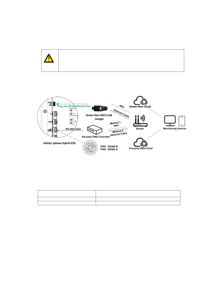
    For example, whether the battery is recharged every 8 months or every 12 months, it can only be recharged a maximum of three times within three years. If the battery has not been recharged within three years, it is recommended that the battery pack be discarded.
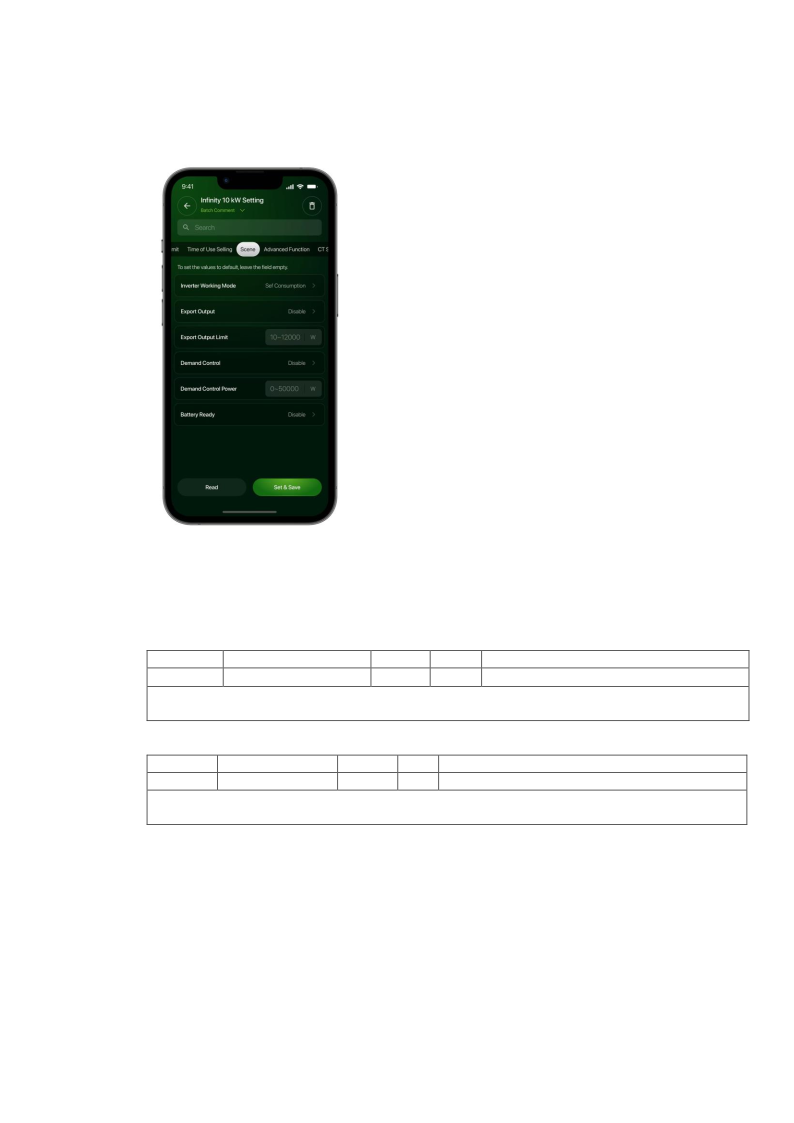
    Lithium-ion batteries lose capacity during storage. After 12 months of storage at the intended storage temperature, the capacity generally falls irreversibly by 3– 10%. Batteries with less than 100% capacity after storage cannot pass the discharge testing and acceptance testing.
    9.3
    Recharging a Battery
    If a battery has not been charged for two weeks or more after a deep discharge, or the SOC of a battery is less than 50% after a long period of storage, the battery must be charged to 50%.
    WARNING
    Before charging the battery, check it for deformation, case damage, or leakage, and if you find any of these things, do not charge the battery.
    NOTE
    If the SOC of a battery pack is not less than 50% after more than 12 months of storage, it is not necessary to recharge the battery.
    NOTES
    Prepare a cross screwdriver and insulated rubber gloves.
    111

    Page 112

    Original PDF
    CAUTION
    When you connect the power wires, wear insulated rubber gloves.
    PROCEDURE
    Step 1. Connect power cables to the battery charger correctly. The maximum number
    of battery pack connected parallel is 4.
    Step 2. Press the battery “start key” for 1~3 seconds to start the battery pack. Check
    the LED on the battery “start key” is on.
    Step 3. Turn on the battery charger.
    Step 4. Set charging parameter on the battery charger.
    Case #1, One battery pack is charged. Set the charge limited voltage 57.6V; Set the
    charge limited current 50A;
    Case #2, Two ~ Four battery packs are charged. Set the charge limited voltage
    57.6V; Set the charge limited current 100A;
    Step 5. After the battery is charged, switch off the battery charger and press the
    battery “start key” for 1~3 seconds to switch off the battery pack.
    10
    Limited Warranty
    If the equipment fails during the warranty period, Company and its authorized partners will provide free service or replace the unit or part with a new one.
    10.1
    What This Warranty Covers
    During the warranty service, the professional personnel certified by Company or its authorized partners will determine the problem based on the current status of the equipment, confirm the time required for repair or replacement, and complete the repair or replacement within the agreed time.
    If a unit or part is replaced, the replaced unit or parts will be recycled and disposed of by Company or its authorized partners.
    The replacement unit or parts provided by Company are determined by the inventory and may not be brand new, but are bound to be in good working condition and at least functionally equivalent to a brand new unit or part.
    The replacement unit or part will be warranted for the remainder of the original warranty period of the equipment.
    112

    Page 113

    Original PDF
    10.2
    How to Obtain Warranty Service
    If the equipment does not function as warranted during the warranty period, you can contact Company or its authorized partners to obtain warranty service.
    10.3
    Customer Responsibility for Warranty Service
    To obtain warranty service, you must take these steps:
    Step 1.
    Provide the purchase invoice to prove that the whole unit or parts are still under warranty.
    Step 2.
    Make sure that the nameplate on the equipment is intact and legible.
    Step 3.
    Make sure that the installation, modification, replacement, or removal of the whole unit or part of the equipment has been done by professional personnel certified by Company or its authorized partners.
    Step 4.
    Make sure that the equipment has been operated in the intended environment described in this manual or other documents provided by Company.
    Step 5.
    Make sure that no non-standard parts or parts not supplied by Company are used in the equipment.
    Failure to comply with any of the above information, Company or its authorized partners have the right to refuse to provide warranty service.
    10.4 Limitation of Liability
    Company has the right to refuse to honor the quality warranty for any of the following reasons:
    • Damage during transportation, including paint scratches caused by friction inside
    the package during transportation, and damage sustained while being transported by you or a third party commissioned by you.
    • Operation of the equipment in an environment other than the intended environment
    described in this manual or other documents provided by Company.
    • Failure or damage caused by installation, repair, modification, or disassembly
    carried out by anyone other than professional personnel certified by Company or its authorized partners.
    • Failure or damage caused by the use of non-standard components or other
    components not provided by Company.
    Company may charge a fee for repair service if you request repair of the equipment in any of the following circumstances:
    • Installation and use beyond the scope of the relevant standards.
    • Damage caused by unexpected natural factors.
    11
    Emergency Procedure
    An emergency is a situation involving a major incident or the possibility of a major
    113

    Page 114

    Original PDF
    incident that cannot be handled according to normal procedures and requires immediate action to limit or address the consequences.
    This section describes emergencies that may be encountered when you are using the INF-4-0/INF-5-0/INF-6-0/INF-8-0/INF-10-0/INF-10-0-BE/INF-12-0 energy storage system and how to handle such emergencies.
    11.1 General Handling
    If an emergency occurs, remember the following:
    • The grid main switch that supplies power directly to the BESS must be turned off.
    • All load switches in the BESS must be turned off.
    • The battery switch must be turned off.
    • If you want to open the inverter or the battery pack after the power is turned off,
    to prevent possible fatal personal injury, use a properly calibrated voltage meter to measure the voltage at the input terminals, wait approximately 15 minutes until the DC link capacitors inside the battery pack is completely discharged, and then open the top cover to repair.
    WARNING
    Before operating the equipment, make sure that the BESS is not supplied with grid power.
    11.2
    Potential Emergencies
    11.2.1
    Battery Leakage
    If the battery pack leaks electrolyte, avoid contact with the leaking liquid or gas. If you contact with the leaking substance, take the measures listed in Table 10-1 immediately.
    Table 11-1 Measures to Solve Battery Leakage Emergency
    Exposure
    Measures
    Inhalation
    Evacuate contaminated area, and then seek medical attention.
    Flush eyes with running water for five minutes, and then seek medical attention.
    Eye Contact
    Wash the affected area thoroughly with soap and water, and then seek medical attention.
    Skin Contact
    Ingestion
    Source wording: Induce vomiting, and then seek medical attention.
    11.2.2
    Fire or Explosion
    If a fire occurs in the area where the battery pack is installed, take the following measures.
    114

    Page 115

    Original PDF
    WARNING
    Batteries can explode when heated over 150°C. Toxic gases can leak when a battery pack burns. DO NOT approach. However, because the batteries contain only a small amount of oxygen and all batteries are equipped with explosion- proof valves, battery explosions are unlikely to occur.
    Table 11-2 Handling with Fire
    Handling with Fire
    Description
    The source states that a respirator is not usually required. For a battery fire it lists a specialized extinguisher such as Noves 1230, FM-200, or a dioxin extinguisher. For a fire with another cause it lists a regular ABC extinguisher.
    Fire Extinguishing Agent
    If a fire occurs while charging a battery, turn off the battery pack circuit breaker and turn off the charging power if it is safe to do so. If the battery pack is not on fire, the fire should be extinguished before the battery pack catches fire. If the battery pack is on fire, do not attempt to extinguish the fire. Instead, evacuate personnel immediately.
    Extinguishing Instructions
    If the battery is in a dry environment, put the damaged battery in an isolated area and call the local fire department or service engineer. If the battery is in a wet environment, DO NOT touch anything if any part of the battery, such as the inverter or cables, is submerged. DO NOT use the submerged battery. Contact a service engineer.
    Methods of Handling Accidents
    115

    Page 116

    Original PDF
    11.3
    Emergency Handling Plan
    If an emergency occurs, follow this emergency handling plan:
    Step 1. Turn off the AC circuit breakers.
    Step 2. Check the control power supply. If there is no problem, supply power to
    the inverter again to find the cause.
    Step 3. Record the details related to the fault so that Company can analyze
    and rectify the fault. DO NOT operate the equipment before the fault is rectified. Please contact Company as soon as possible.
    12
    Disposal
    When the system reaches the end of its service life, follow these step to dispose of the equipment:
    Step 1. Uninstall the system:
    1.1 Disconnect all power sources.
    1.2 Disassemble all parts of the system from top to bottom.
    Step 2. Dispose of all the parts. DO NOT dispose of the battery packs as regular
    household waste.
    This symbol means that the labeled equipment must not be disposed of as regular household waste. It must be disposed of at an electrical and electronic equipment-recycling center.
    NOTICE
    If you need to replace a battery pack, you should request a new dangerous goods package, pack the battery pack, and then have the supplier pick it up.
    Company does not recycle batteries. Please contact your local recycling organization for disposal. If there is no local recycling organization, you should contact the nearest recycling organization in your country.
    13
    Specifications
    13.1
    Hybrid Inverter
    Dimension (W × H × D, mm)
    725 × 490 × 245
    Net Weight (kg)
    4–6 kW: 40, 8–12 kW: 43
    ( Does not include the weight of the base )
    Operating Temperature
    -25°C to +60°C, derated over 40°C
    Operating Relative Humidity
    0–95% (No condensation)
    ≤ 3000 m
    Operating Altitude
    116

    Page 117

    Original PDF
    Protective Class
    Class I
    Pollution degree classification External (PD3), Internal (PD2)
    Overvoltage Category
    II (DC side), III (AC side)
    Topology
    High Frequency Isolation
    Cooling
    Natural Convection
    Display
    LED/APP
    Communication Interface
    RS485, CAN2.0, Wi-Fi, and 4G
    Ingress Protection
    IP66
    Max. Conversion Efficiency
    (From Battery)
    93.5%
    Max. Conversion Efficiency
    (From PV)
    4–6 kW 96.6 % / 8–12 kW 97.2 %
    Euro Efficiency
    4–6 kW 94.5 % / 8–12 kW 95.5 %
    MPPT Efficiency
    99.5 %
    • Short Circuit Protection
    • AC Leakage Fault Protection
    • Grounding Fault Protection
    • Anti-islanding Protection
    Protection Function
    • Overload Protection
    • Surge Protection
    • DC Polarity Protection
    • EN50549-10
    • VDE-AR-N4105
    • VDE0126-1-1 More grid regulation certifications are to be made available. Please contact Company for the latest information.
    Grid Regulation
    • IEC/EN 62109-1&2
    • IEC62040-1
    Safety Regulation
    • IEC62619
    • EN61000-6-1
    • EN61000-6-2
    • EN61000-6-3
    • EN61000-6-4
    EMC
    • EN61000-3-2
    • EN61000-3-3
    • EN61000-3-11
    • EN61000-3-12
    117

    Page 118

    Original PDF
    100 ADC/100 ADC
    120 ADC/120 ADC
    13.2 Battery Terminal Input /Output
    INF-4-0
    INF-5-0
    INF-6-0
    Battery Type
    Lithium or lead-acid batteries
    Voltage Range
    44–58 VDC
    Rated Voltage
    51.2 VDC
    Maximum
    Charge/
    Discharge
    Current
    120ADC/150 ADC
    Rated Charge/
    Discharge Power
    4000 W/4000 W
    5 000 W/5 000 W
    6 000 W/6 000 W
    INF-8-0
    INF-10-0
    INF-10-0-BE
    INF-12-0
    Battery Type
    Voltage Range
    Rated Voltage
    Maximum
    Charge/
    Discharge
    Rated Charge/
    Discharge Power
    Lithium or lead-acid batteries
    44–58 VDC
    51.2 VDC
    160 ADC/
    200 ADC
    200 ADC/
    240 ADC
    200 ADC/
    240 ADC
    200ADC/
    240 ADC
    8000 W/
    8000 W
    10 000 W/
    10 000 W
    10 000 W/
    10 000 W
    10 000 W/
    12 000 W
    118

    Page 119

    Original PDF
    13.3 PV Input
    INF-4-0
    INF-5-0
    INF-6-0
    Vmax. PV
    1000 VDC
    Rated Voltage
    720 VDC
    PV Start Voltage
    200 VDC
    MPPT Voltage Range
    140–950 VDC
    MPPT Range (Full Load)
    200–800 VDC
    230–800VDC
    250–800 VDC
    MPPT Tracker/Strings
    2
    Max. Continuous PV Input Current
    20 ADC × 2
    Isc PV
    25 ADC × 2
    Max. inverter backfeed current to PV array
    0 ADC
    Max. Back feed Current
    0 ADC
    Max. Continuous PV Input Power
    10 000 W
    11 000 W
    12 000 W
    INF-8-0
    INF-10-0
    INF-10-0-BE
    INF-12-0
    Vmax. PV
    1000 VDC
    Rated Voltage
    720 VDC
    PV Start Voltage
    200 VDC
    MPPT Voltage Range
    140–950 VDC
    MPPT Range (Full Load)
    320–800 VDC
    290–800 VDC
    320–800VDC
    350–800 VDC
    MPPT Tracker/Strings
    2
    Max. Continuous PV Input Current
    20 ADC × 2
    Isc PV
    25 ADC × 2
    Max. inverter backfeed current to PV array
    0 ADC
    Max. Back feed Current
    0 ADC
    Max. Continuous PV Input Power
    16 000 W
    20 000 W
    20 000 W
    22 000 W
    119

    Page 120

    Original PDF
    13.4 Grid Terminal Input /Output
    INF-4-0
    INF-5-0
    INF-6-0
    Rated Voltage
    220/230/240 VAC
    Rated Frequency
    50 Hz /60 Hz
    Maximum Continuous Input Current
    21 AAC
    22.6 AAC
    22.6 AAC
    Maximum Continuous Input Power
    10 000 W
    11 000 W
    12 000 W
    Rated Output Current
    5.8 AAC
    7.3 AAC
    8.7 AAC
    Maximum Continuous Output Current
    13.1 AAC
    13.1 AAC
    13.1 AAC
    Power factor (Cos phi), Adjustable
    0.8 leading–0.8 lagging
    Rated Output Power
    4 000 W
    5 000 W
    6 000 W
    Maximum Continuous Output Apparent Power
    4 400 VA
    5 500 VA
    6 600 VA
    Grid Port Overcurrent Protection
    40 A
    INF-8-0
    INF-10-0
    INF-10-0-BE
    INF-12-0
    Rated Voltage
    220/230/240 VAC
    Rated Frequency
    50 Hz /60 Hz
    Maximum Continuous Input Current
    35 AAC
    35 AAC
    35 AAC
    35 AAC
    Maximum Continuous Input Power
    16 000 W
    20 000 W
    20 000 W
    22 000 W
    Rated Output Current
    11.6 AAC
    14.5 AAC
    14.5 AAC
    17.4 AAC
    Maximum Continuous Output Current
    26.1 AAC
    26.1 AAC
    26.1 AAC
    26.1 AAC
    Power factor (Cos phi), Adjustable
    0.8 leading–0.8 lagging
    Rated Output Power
    8 000 W
    10 000 W
    10 000 W
    12 000 W
    Maximum Continuous Output Apparent Power
    8 800 VA
    11 000 VA
    10 000 VA
    13 200 VA
    Grid Port Overcurrent Protection
    63 A
    120

    Page 121

    Original PDF
    13.5
    BACK UP load Terminal Output
    INF-4-0
    INF-5-0
    INF-6-0
    Rated Voltage
    230 VAC
    Rated frequency
    50 Hz/60 Hz
    Rated Output Current
    5.8 AAC
    7.3 AAC
    8.7 AAC
    Maximum Continuous Output Current
    13.1 AAC
    13.1 AAC
    13.1 AAC
    Power factor (Cos phi)
    0.8 leading–0.8 lagging
    Rated Continuous Output Power
    4 000 W
    5 000 W
    6 000 W
    Maximum Output Apparent Power
    4 000 VA
    5 000 VA
    6 000 VA
    BACK UP load Overcurrent Protection
    32 A
    INF-8-0
    INF-10-0
    INF-10-0-BE
    INF-12-0
    Rated Voltage
    230 VAC
    Rated frequency
    50 Hz/60 Hz
    Rated Output Current
    11.6 AAC
    14.5 AAC
    14.5 AAC
    17.4 AAC
    Maximum Continuous Output Current
    26.1 AAC
    26.1 AAC
    26.1 AAC
    26.1 AAC
    Power factor (Cos phi)
    0.8 leading–0.8 lagging
    Rated Continuous Output Power
    8 000 W
    10 000 W
    10 000 W
    12 000 W
    Maximum Output Apparent Power
    8 000 VA
    10 000 VA
    10 000 VA
    12 000 VA
    BACK UP load Overcurrent Protection
    40 A
    121

    Page 122

    Original PDF
    13.6 Battery Pack
    normal
    Operations
    BMS
    Physical parameters
    Battery specification
    INF-0-5.12 / BP48100PF1A-G2
    Battery capacity
    5.12 kWh
    Battery type
    LFP
    Rated voltage
    51.2V
    Operating voltage range
    44.8–57.6V
    Maximum charging current
    50A (0.5C)
    Maximum discharging current
    80A (0.8C)
    Operating temperature range
    Charge
    -10°C~+50°C
    Discharge
    -10°C~+50°C
    Storage temperature range
    0°C~+35°C
    Relative humidity
    0%~95%(No condensation)
    Protective class
    I
    Short circuit ratings
    360A 300us
    Maximum number of batteries
    Maximum 8 batteries in parallel
    Monitored item
    System voltage, current, battery voltage, battery temperature, PCBA temperature measurement
    Communication mode
    CAN
    Ventilation mode
    Passive cooling
    Weight (kg)
    50.5
    Size (W×H×D) mm
    725*165*370(Excluding handles)
    Water resistance level
    IP65
    Reference to standards
    IEC 62619
    IEC 62477
    IEC 62040
    IEC61000-6-1//3
    UN38.3
    122

    Page 123

    Original PDF
    14
    Abbreviations
    A
    AC
    Alternating Current
    AFCI
    Arc-Fault Circuit-Interrupter
    App
    Application
    AWG
    American Wire Gauge
    B
    BESS
    Battery Energy Storage System
    BMS
    Battery Management System
    C
    CT
    Current Transformer
    D
    DC
    Direct Current
    DOD
    Depth of Discharge
    DRED
    Demand Response Enabling Device
    DRM
    Demand Response Mode
    DSP
    Digital Signal Processor
    E
    EMI
    Electromagnetic Interference
    EMS
    Energy Management System
    BACK UP
    Emergency Power Supply
    G
    GFCI
    Ground Fault Circuit Interrupter
    I
    ISO
    Insulation
    123

    Page 124

    Original PDF
    M
    MPPT
    Maximum Power Point Tracker
    P
    PV
    Photovoltaic
    R
    RCD
    Residual Current Device
    RESP
    Response
    RRCR
    Radio Ripple Control Receiver
    S
    SCI
    Serial Communication Interface
    SOC
    State of Charge
    15
    Appendix: Definition of DVC
    Limits of working voltage V
    Decisive voltage
    a.c. voltage
    a.c. voltage
    d.c. voltage
    Classification
    r.m.s. U ACL
    peak U ACPL
    mean U DCL
    (DVC)
    25
    (16)
    35.4
    (22.6)
    60
    (35)
    A*
    50
    (33)
    71
    120
    (70)
    B
    (46.7)
    > 50
    (> 33)
    > 71
    > 120
    (> 70)
    C
    (> 46.7)
    The table values in parentheses are to be used for PCE or portions of PCEs rated for installation in wet locations as addressed in 6.1 for environmental categories and minimum environmental conditions. *DVC-A circuits are allowed under fault conditions to have voltages up to the DVC- B limits, for maximum 0.2 s.
    124